


Commodity Number :
375-261-522-040
Commodity Name :
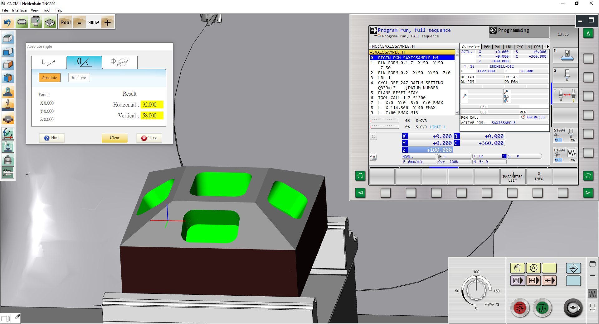
VM Heidenhain TNC640-5A(TBTC) 2022 Professional Version
Commodity Introduction :
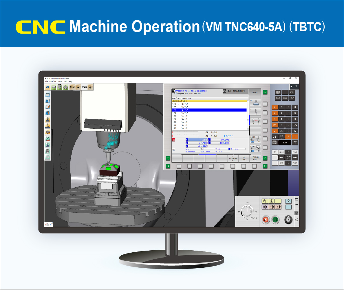
Realistic CNC Controller Function Panel, Modularized Machine Operation Panel, and Machine Simulation. Excellent tool for CNC controller recognition and practicing tool offset.
Use Version :
Subscription Plan:
Commodity Price :
Product Specifications
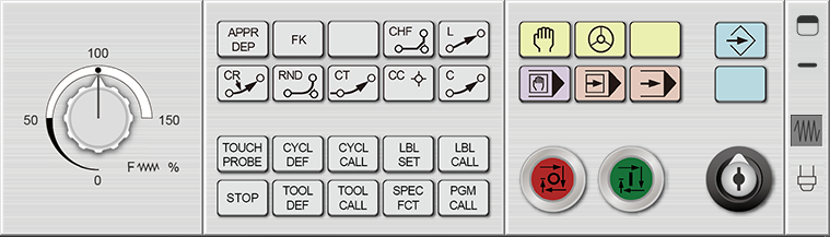
1 CNC Controller Operation Panel Function
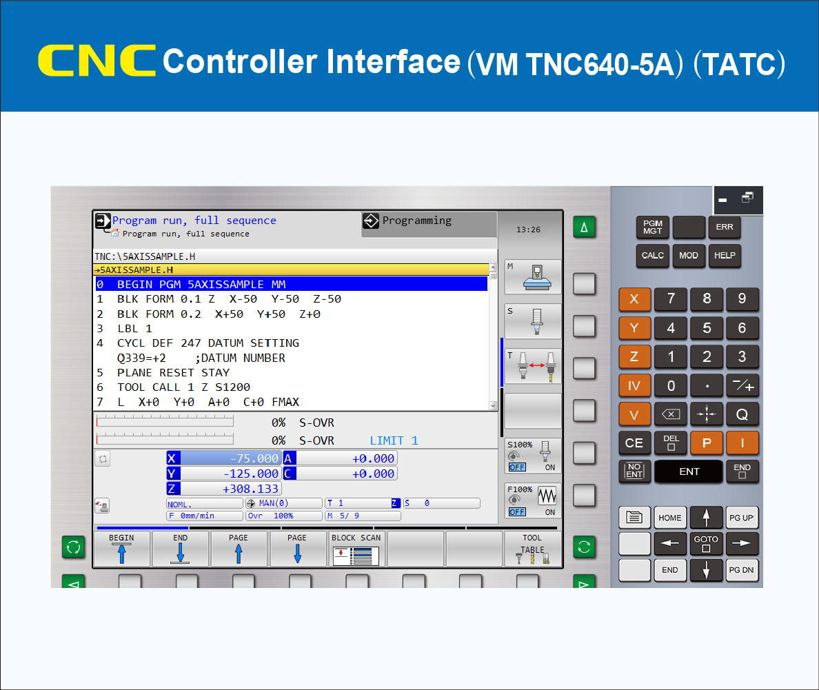
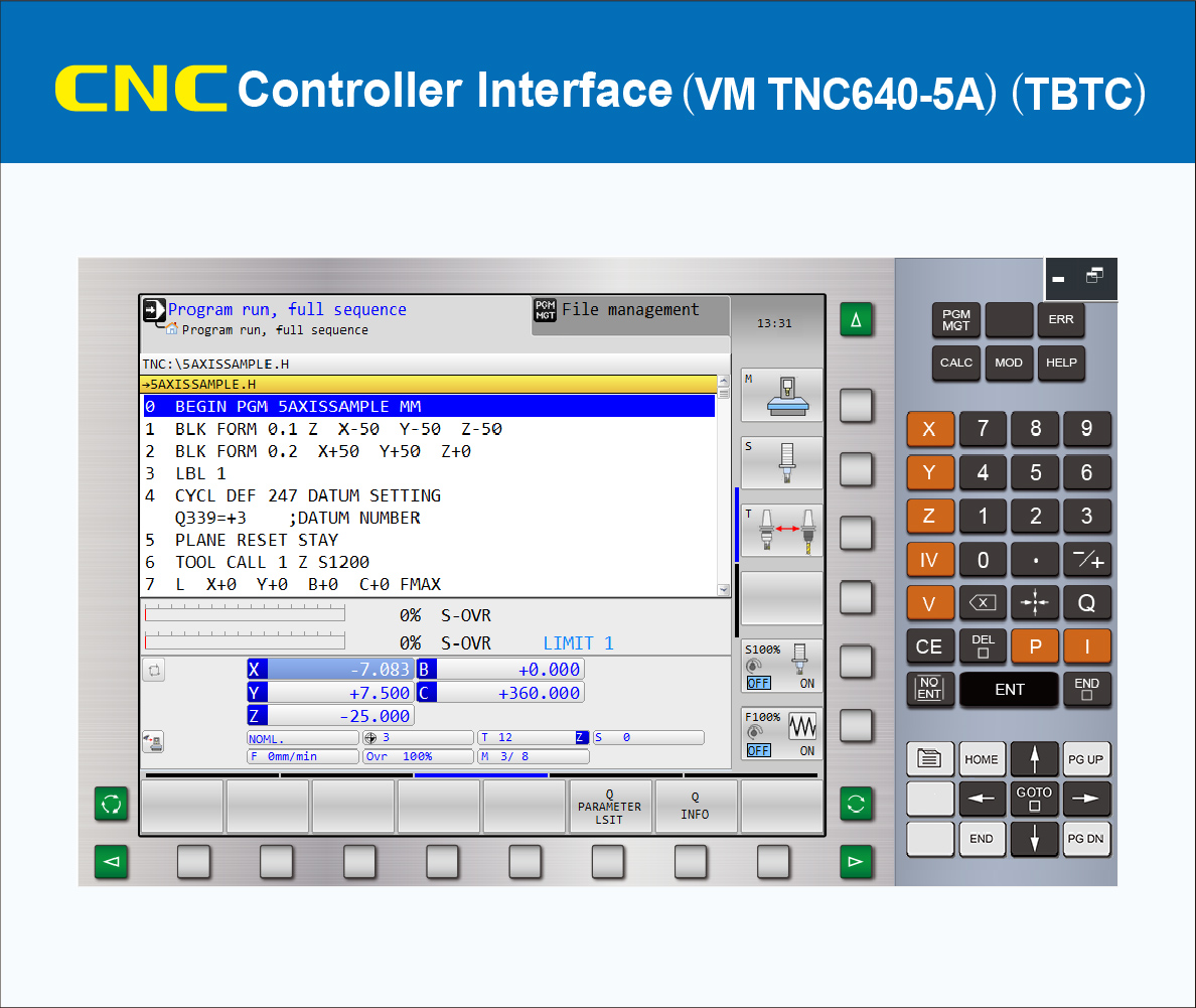
1.01 CNC Controller Simulation Heidenhain TNC640 5 Axis
1.02 The Operation Panel Function is the complete emulation based on the actual Heidenhain TNC640 CNC machine operation
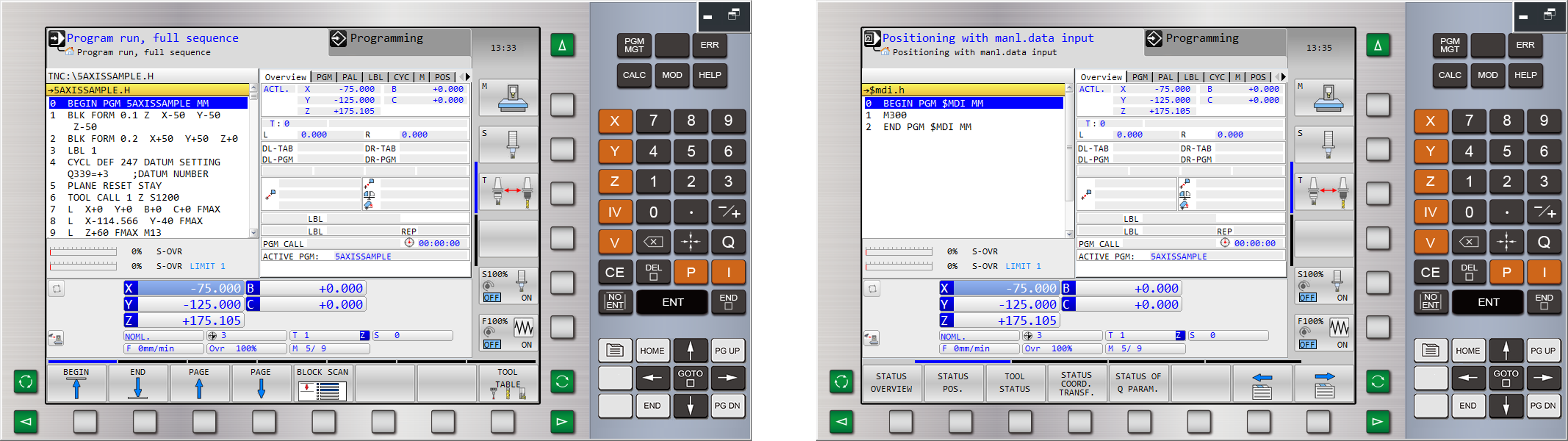
(1) [AUTO] Machining Operation: display absolute coordinate and machining status, block scan, Q INFO
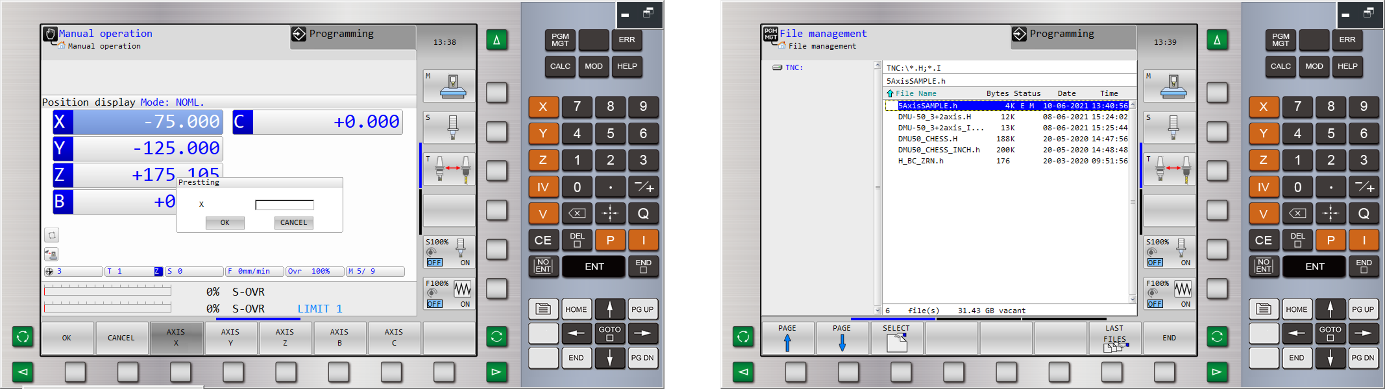
(2) [MDI] Machining Operation: display machine coordinate and machining status, guided program input
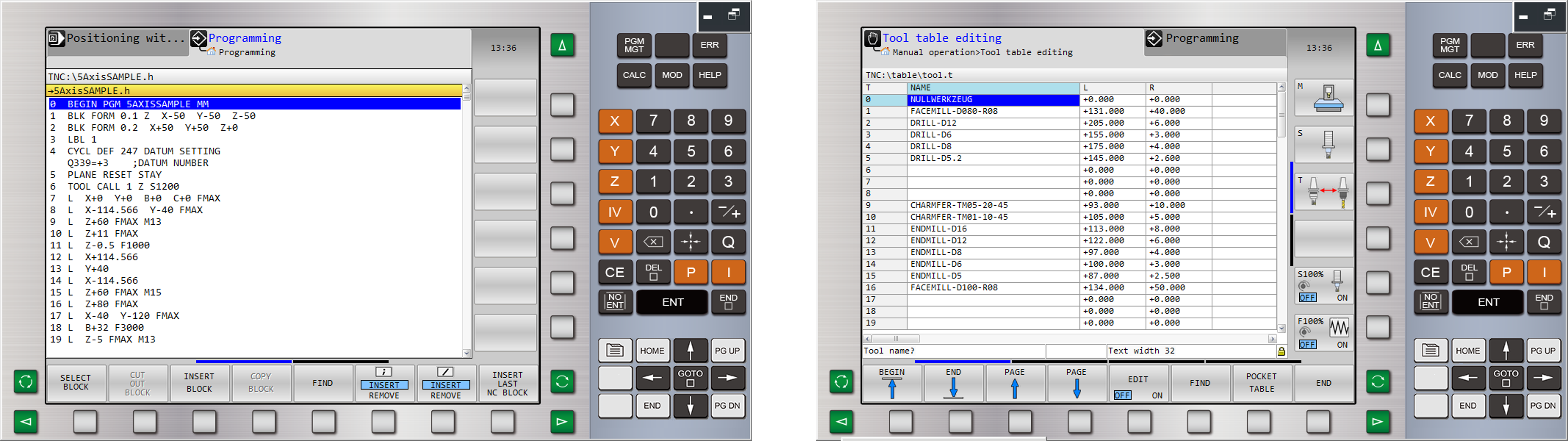
(3) [EDIT] Program editing: Select block, cut out block, insert block, copy block, find, guided program input
(4) [TOOL TABLE] Tool List: Tool data settings and tool offset
(5) [DATUM MANAGEMENT] Work coordinates: Work coordinates settings and alteration.
(6) [PGM] Program management: Select, copy, last files, delete, rename, new file
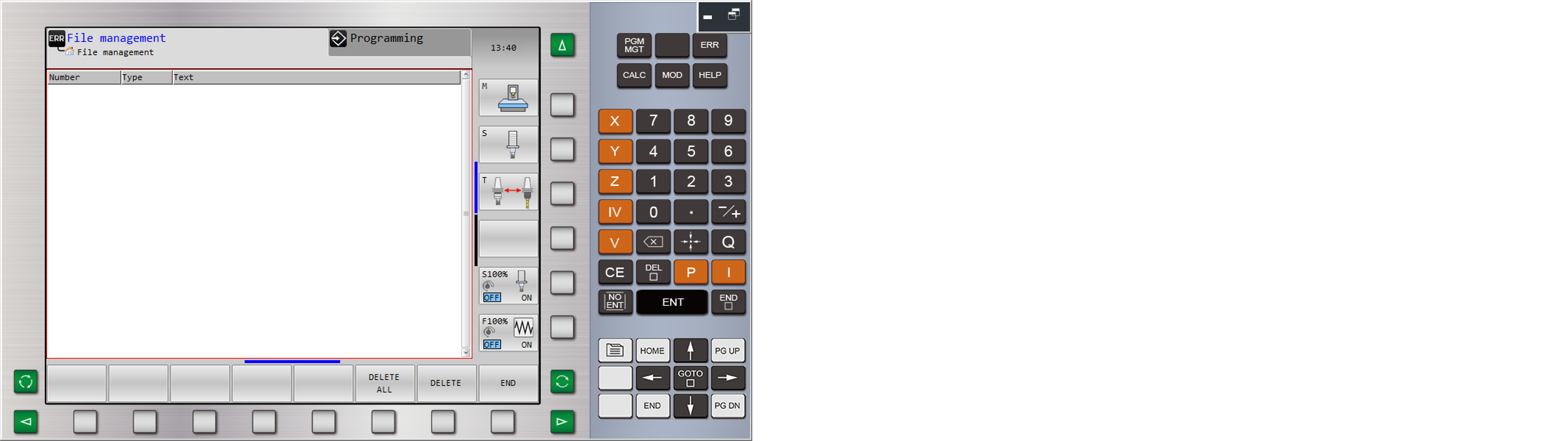
(7) [ERR] Alarm: Alarm list, alarm history
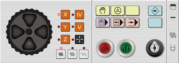
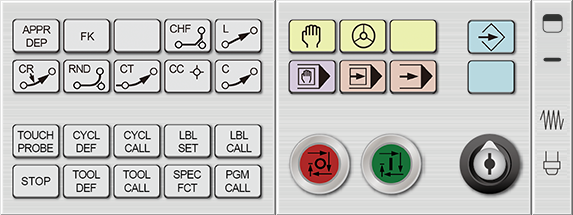
2 CNC Machine Operation Panel
2.01 Mode Select Button Function
(1) [AUTO]
Full sequence mode – Program executes automatically
Single block mode – Program executes by single block
(2) [MDI] Manual Data Input –
For parameter settings and temporary input program
(3) [MANUAL]
MPG mode – Move with handwheel
Rapid mode – Move rapidly with axis movement buttons
(4) [EDIT] Program edit mode –
Edit and alter program content
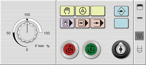
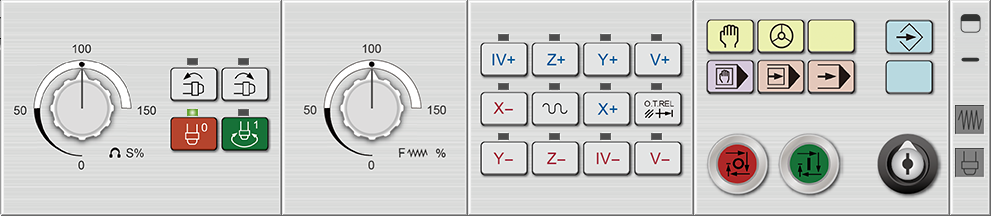
2.02 Feedrate adjustment knob
2.03 Start [CYCLESTART], Pause [HOLD]
2.04 Spindle forward, Spindle reversal, Spindle stop
2.05 Program lock, Emergency stop, Coolant, Safety door open/ close
2.06 Axis movement buttons
[X+], [X-], [Y+], [Y-], [Z+], [Z-],
[IV+], [IV-], [V+], [V-], [RAPID], O.T. Release
2.07 Handwheel, Handwheel feedrate button, Handwheel axis selection button
3 CNC Milling Machine Simulation
3.01 Based on 3D physical construction, the machine model of 5 Axis Vertical Machining Center includes Machine bed, Vise, Z tool setter, Tool, Auto Tool Change ATC
Travel:
X axis 750 mm, Y axis 750 mm, Z axis 650 mm
Rapid:
X axis 18 m/min, Y axis 18 m/min, Z axis 18 m/min
B axis 24 rpm, C axis 24 rpm
Max Cutting Feed:
X axis 6 m/min, Y axis 6 m/min, Z axis 6 m/min
B axis 24 rpm, C axis 24 rpm
3.02 Simulate whole CNC machine with physical machine control panel and dynamic interactive simulation
3.03 Collision detection function: tool and material.
If the tool isn’t rotating, the contact between the tool and the material will be considered a collision

3.04 Simulation speed adjustment: 100%, 160%, 250%, 500%
3.05 Working Table: Single-arm type swivel table (B axis + C axis)
3.06 Workpiece setting
(1) Cubic workpiece dimension:
Max Length= 230mm
Max Width= 200mm
Max Height= 200mm
(2) Cylinder workpiece dimension:
Max Diameter= 120mm
Max Length= 250mm
Max Reach= 200mm
(3) Workpiece position
3.07 Milling, Magazine, Tool setting:
Face Mill Tool, End Mill, Radius Corner Endmill, Ball-Nose Endmill, Chamfer Endmill, Edge Finder, Spot Drill, Drill, Tap, Thread Mill, Rough Boring, Finish Boring
3.08 Magazine install: Tool install, modify, delete
3.09 Standard view : Top (XY), Front (ZX), Side, (YZ), 3Dimension (ISO)
3.10 Universal view setting: Material range, Machine bed range, machine range
3.11 Operator view: Shift, Rotate, Zoom in/out
3.12 Tool offset operation: Z axis setting, Photoelectric Length tool setter, X Y axis setting, Photoelectric Edge finder
Standard Version Features (included)
3.21 Based on 3D physical construction, the machine model of 5 Axis Vertical Machining Center includes Machine bed, Spindle head, Vise, Z axial tool setter, Tool, Auto Tool Changer ATC.
3.22 Simulated design including coolant fluid, cutting the workpiece until chips spattering, audio (tool movement, cutting sound effect, spindle rotation, alarm)
3.23 Collision detection: tool and material, vise, swivel table, collision detection
3.24 Simulation Speed Adjustment: 50%, 100%, 250%, 500%
3.25 Workpiece linear measurement function: length, width, height, linear path
3.26 Quick reset to Factory Setting
3.27 CNC Program Import/Export function
Professional Version Additional Features
3.31 Based on 3D physical construction, the machine model of 5 Axis Vertical Machining Center includes Machine bed, metal shell, auto-door, spindle head, vise, Z axial tool setter, tool, Auto Tool Changer
3.32 Machine case display/hide
3.33 Program zero point display according to tool offset value
3.34 Save and import configuration to completely save and resume the settings status as a reference of examination and correction
3.35 Workpiece material: save and load in (format: STL)
3.36 Tool setting: add, modify, delete, tool data import/export
3.37 Magazine Install: Import/Export, Common Magazine
3.38 Simulation Speed Adjustment: 10%, 50%, 100%, 160%, 250%, 500%, 900%, 990%, MAX
3.39 Limit the simulation speed within the range of 500% to help students with their program check and execution
3.40 Workpiece setting: Workpiece color, block height, Vise dimension
3.41 Workpiece dimension measure: angle measurement (Absolute, both sides angle), arc(three points circle)
3.42 Equipped with machine produce status and immediate monitoring management system
3.43 Spindle speed and feedrate detection function:
(1) Spindle spins correctly and spindle speed is in regulated range.
(2) Feedrate in regulated range.
3.44 Tool and material collision detection function:
(1) Spindle not spinning or incorrect spinning direction and tool and material touches is regarded as collision.
(2) Non-cutting part of tool touches material is regarded as collision.
(3) Feedrate too high and over permitted range is regarded as collision.
3.45 Collision detection:
Tool and material, vise, swivel table, collision detection
Spindle and material, vise, swivel table, collision detection
4 CNC 5 Axis Program Simulation
4.01 Program executes cutting simulation includes 3+2 Axis
4.02 Heidenhain program function
(1) Interpolation: L C CR CT
(2) Dwell: CYCL DEF 9
(3) Plane Selection: TOOL CALL X/Y/Z
(4) Tool call and tool definition command: TOOL CALL,TOOL DEF
(5) Tool Radius Compensation Command: R0 RR RL R+ R-
(6) Input system inches/metric: MM INCH
(7) Absolute/Incremental Dimension: IX_ IY_ IZ_...
(8) Supports drilling cycles: CYCL DEF 200, CYCL DEF 203, CYCL DEF 205, CYCL DEF 240, CYCL DEF 241
(9) Supports tapping cycles: CYCL DEF 206, CYCL DEF 207, CYCL DEF 209
(10) Supports reaming and boring cycles: CYCL DEF 201, CYCL DEF 202, CYCL DEF 204, CYCL DEF 208
(11) Datum shift CYCL DEF 7
(12) Datum setting CYCL DEF 247
4.03 M Code auxiliary function
(M00) Program stop (M03) Spindle reversal
(M01) Optional stop (M04) Spindle forward
(M02) End of program (M05) Spindle stop
(M06) Auto tool change
(M30) End of program
(M91) Coordinates referenced to machine datum within the positioning block
(M92) Coordinates referenced to machine reference point within the positioning block
(M99) Block wise cycle call
(M116) Feed rate for rotary axes in mm/min
(M117) Feed rate for rotary axes in deg/min
(M126) Shortest-path traverse of rotary axes
(M127) Shift movement between command and actual position
(M136) Feed rate F in millimeters per spindle revolution, mm/rev
(M137) Feed rate F in millimeters per minute, mm/min
Standard Version Features (included)
4.21 Program executes cutting simulation includes 4 axis synchronicity
4.22 Heidenhain program function:
(1) Polar coordinates motion command: LP CP CR CTP
(2) Support auto corner C_ and R_ of G01 axis right angle
(3) Inclined plane machining: AXIAL, EULER, POINT, PROJECT, REL.SPA., RESET, SPATIAL, VECTOR
4.23 M Code auxiliary function
(M08) Coolant fluid on (M09) Coolant fluid off
(M13) Spindle Forward & Coolant on
(M14) Spindle Reverse & Coolant on
Professional Version Additional Features
4.31 Program executes cutting simulation includes 4&5 axis synchronicity
4.32 Heidenhain program function:
(1) Support pocket milling command CYCL DEF 251, CYCL DEF 252, CYCL DEF 253, CYCL DEF 254
(2) TCPM: M128
4.33 G Code function (ISO code)(*.I):
(1) Interpolation: G00 G01 G02 G03 G05 G06 G07
(2) Polar coordinates motion command:G10 G11 G12 G15 G16
(3) Dwell: G04
(4) Plane Selection: G17 G18 G19
(5) Tool Radius Compensation Command: G40 G41 G42
(6) Tool call and tool definition command: T
(7) Input system inches/metric: G70 G71
(8) Absolute/Incremental Dimension: G90 G91
(9) Support G01 auto corner C_(G24) and R_(G25) for any angle
(10) Work Coordinates: G53, G54, G247
(11) Supports drilling commands: G200, G203, G205, G240, G241
(12) Supports tapping commands: G206, G207, G209
(13) Supports reaming and boring commands: G201, G202, G204, G208
(14) Supports pocketing commands:G251, G252, G253, G254
(15) Inclined plane machining: AXIAL, EULER, POINT, PROJECT, REL.SPA., RESET, SPATIAL, VECTOR
(16) TCPM: M128
(17) Point pattern machining cycle: G220, G221
(18) Special cycle command: G04, G62
4.34 MACRO function
(1) Logic Operations – equal to =,
(2) Conditional Branches – Conditional Jump IF [conditional] GOTO n