Commodity Number :
353-121-522-046
Commodity Name :
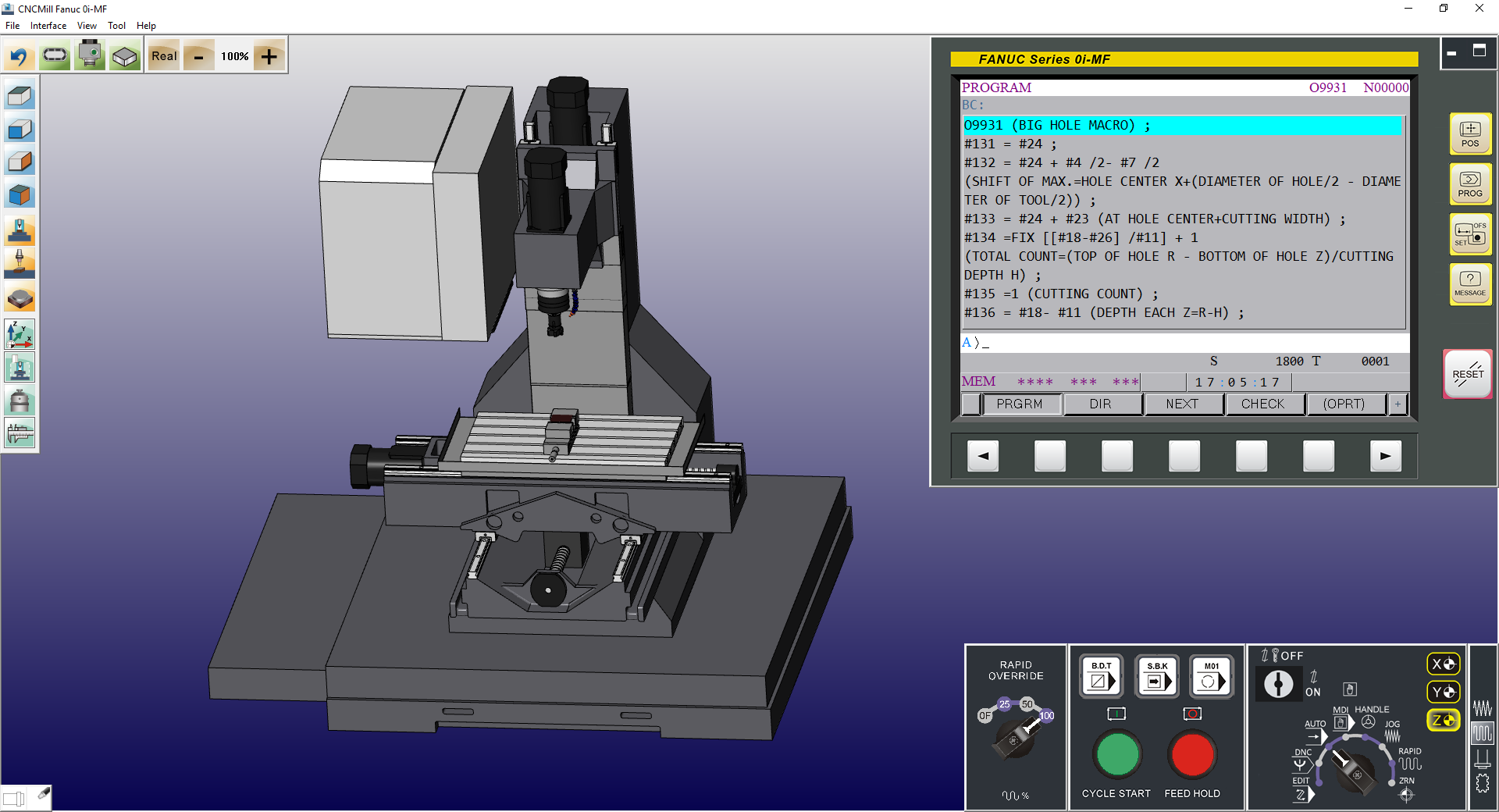
VM Fanuc 0i-MF 2022 Professional Version
Commodity Introduction :
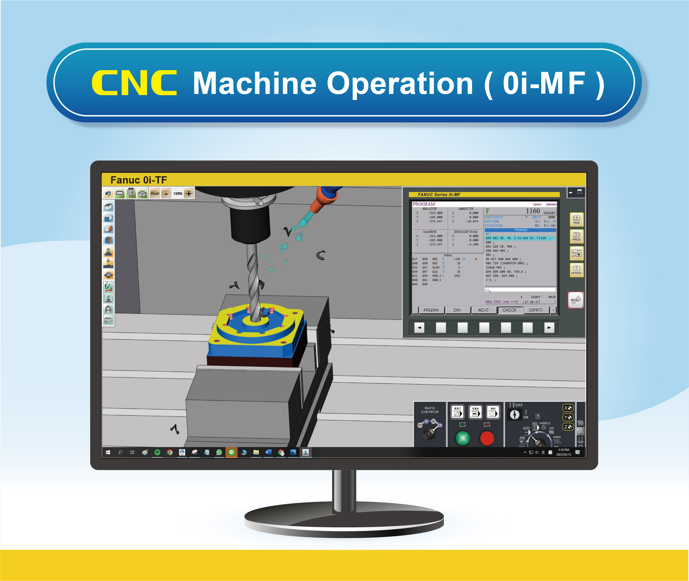
Realistic CNC Controller Function Panel, Modularized Machine Operation Panel, and Machine Simulation. Excellent tool for CNC controller recognition and practicing tool offset.
Use Version :
Subscription Plan:
Commodity Price :
Product Specifications
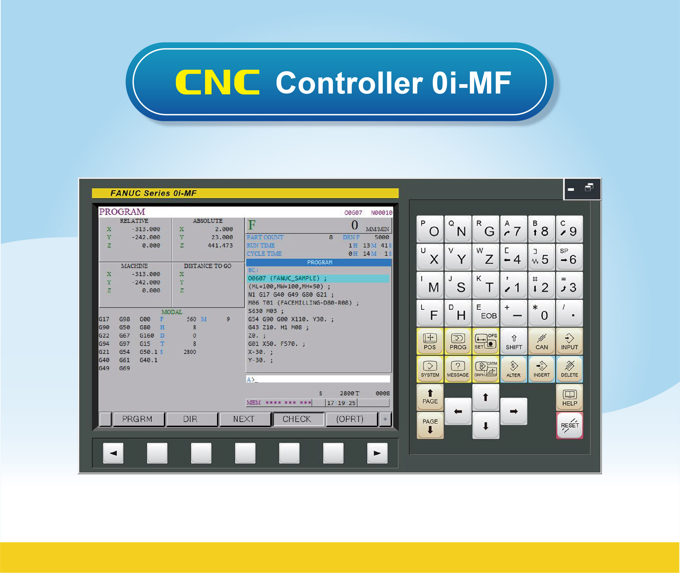
1 CNC Controller Function
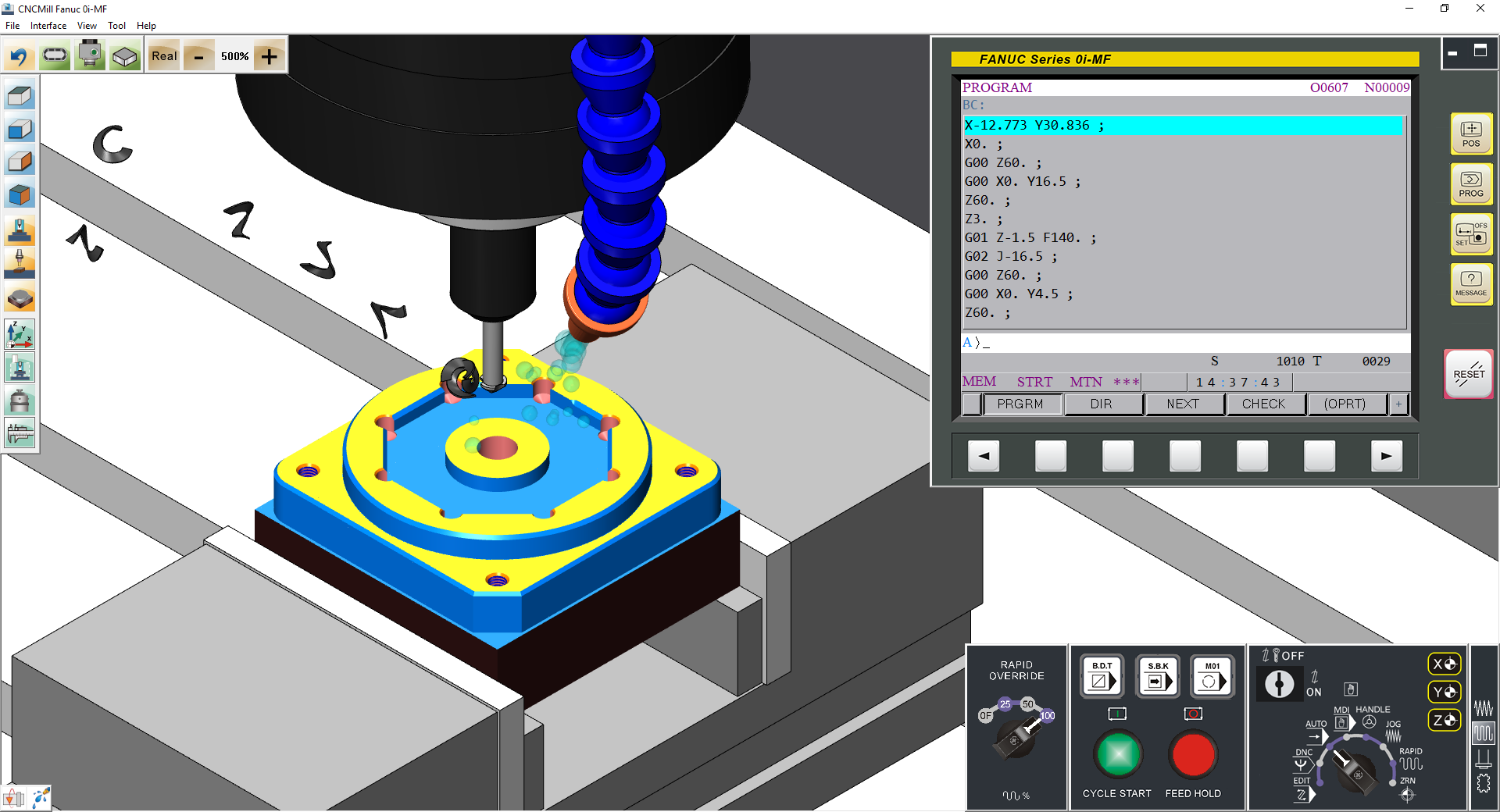
1.01 CNC Operation Simulation Station: Fanuc 0i-MF 3Axes
1.02 The Operation Panel Function is the complete emulation based on the actual CNC machine operation panel
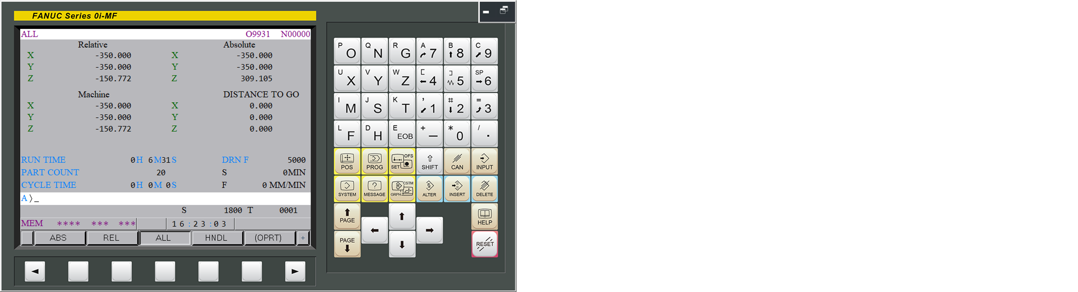
(1) [POS]: machine coordinate, absolute coordinate, relative coordinate, Spindle load
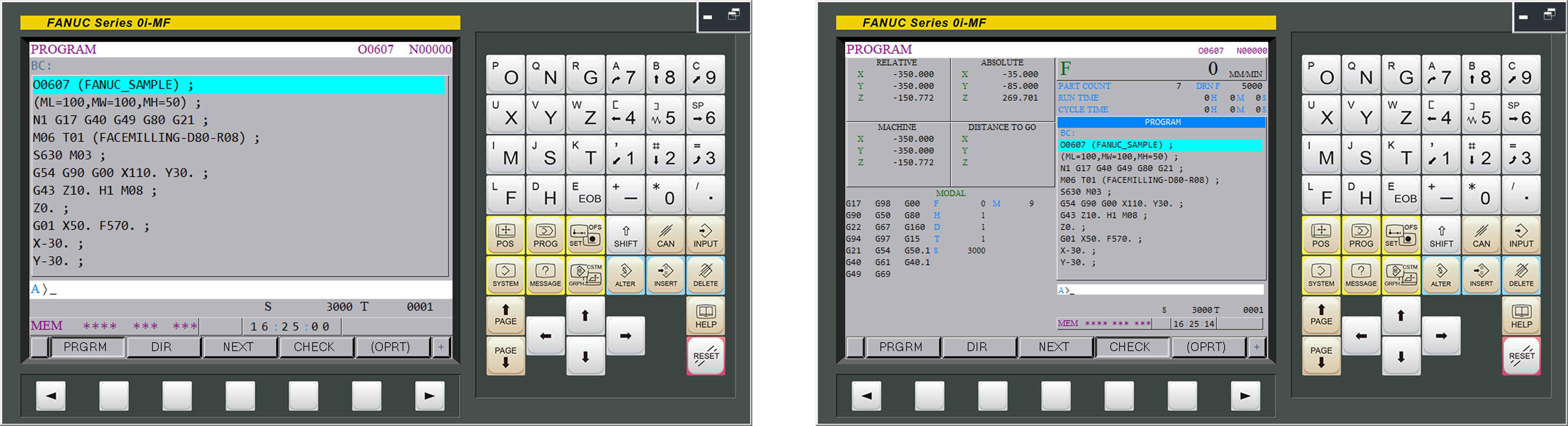
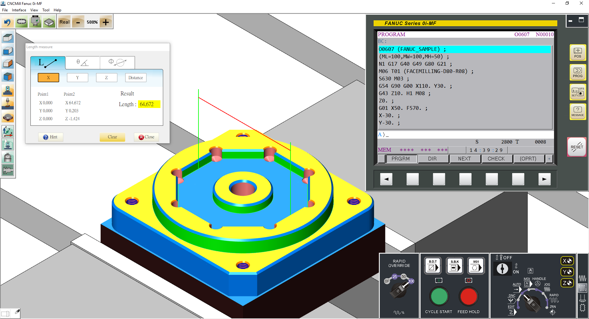
(2) [PROG]
(a) [AUTO]: Program content display, check, current block, next block
(b) [EDIT]: [ALTER][INSERT][DELETE], program lock
(c) Program Transportation, [F input] ,[F output]
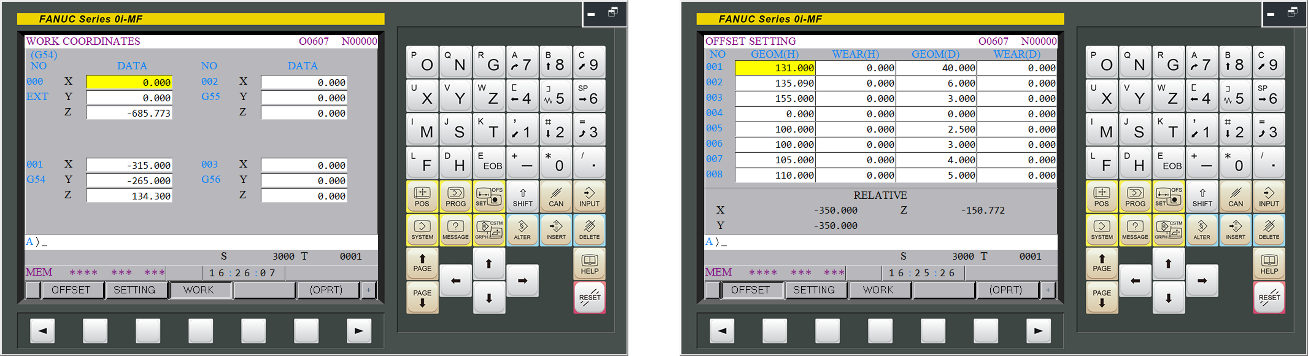
(3) [OFS/SET]: Work coordinate, Tool offset, MACRO variable, Metric/Imperial unit settings
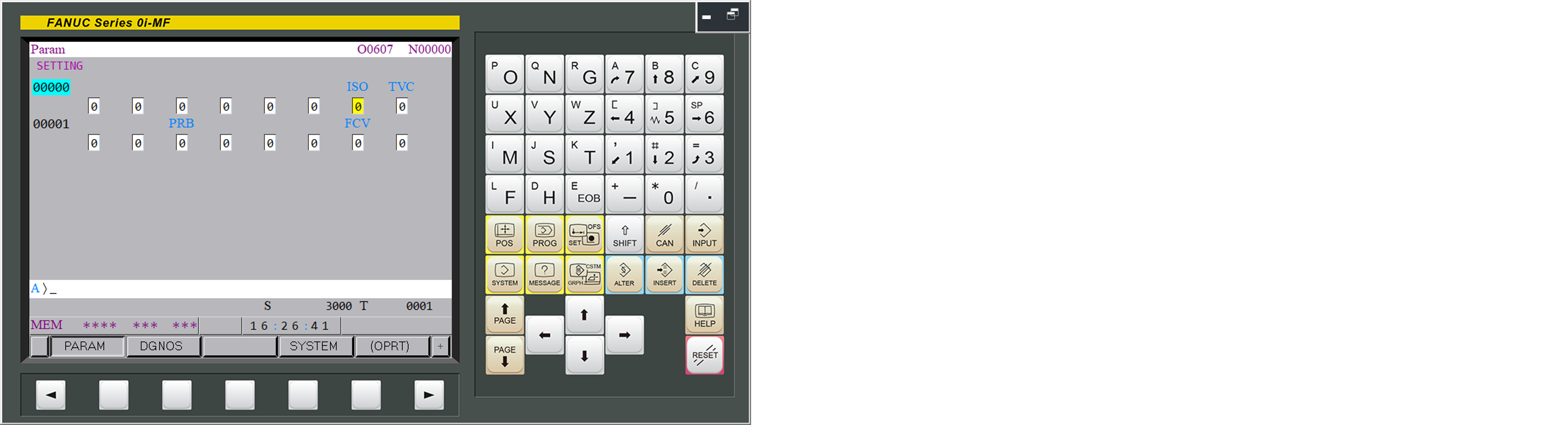
(4) [SYSTEM] parameters: transmission, machine, edit
(5) Alphabetic & Numeric keys, [INPUT], [RESET], [CANCEL]
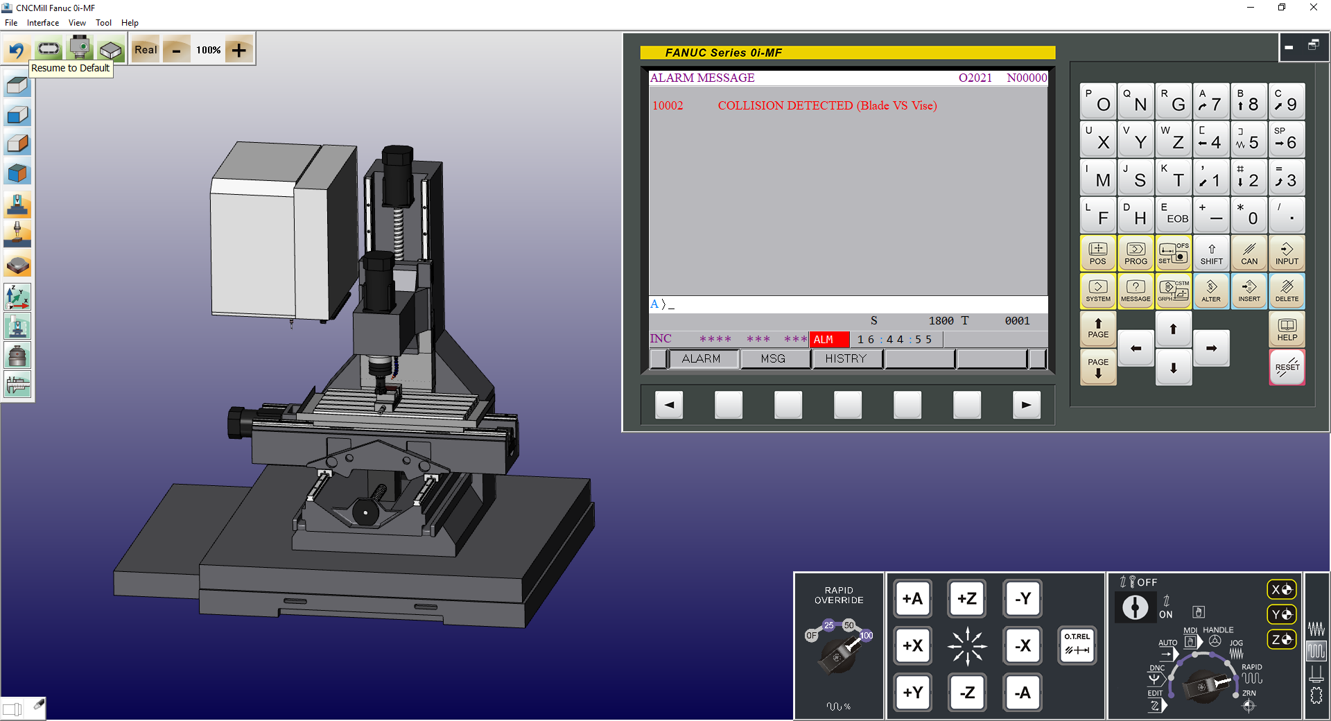
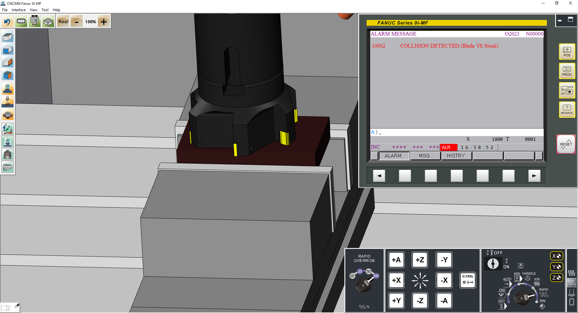
1.03 Alarm display
the alarm codes share the same codes as in the actual machine
(1) E.g.: X axis is over traveled, the alarm code indicates:
”500 OVER TRAVEK:+X”,
While X axis is over traveled , move X axis to the proper position and press [RESET] to clear the alarm
(2) E.g.: 1211 EMG ESTOP, pull up the emergency button to clear alarm
(3) System records the time and the error codes whenever the alarm message is displayed
1.04 RJ45 network transmission function
2 CNC Machine Operation Panel
2.01 Mode Select
(1) [EDIT] Program edit mode – program content modification
(2) [AUTO] Auto execution mode – program auto-run
(3) [MDI] Manual Data Input – for parameter settings and extra codes input
(4) [HANDLE] Manual Pulse Generator-adjustment with handwheel
(5) [JOG] Jog mode – Infeed control with axis buttons
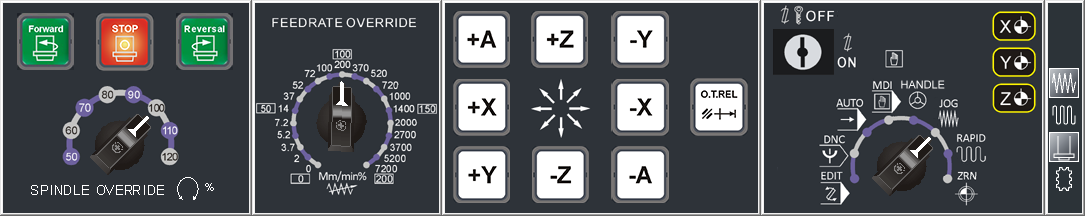
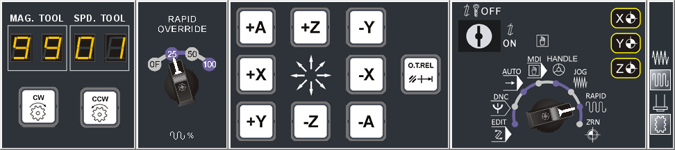
(6) [RAPID] Rapid mode – Rapid Traverse with axis buttons
(7) [ZRN] Zero Point Return – for Axis Offset
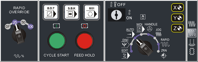
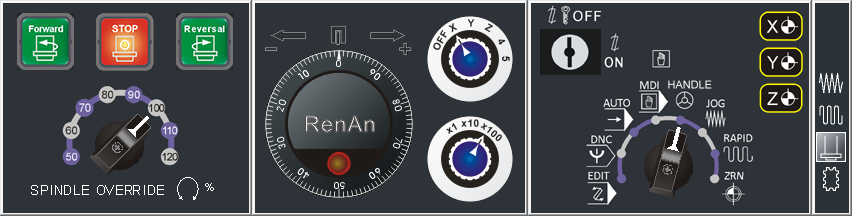
2.02 Switches including: Rapid override, Feedrate Override, Spindle revolution override
2.03 Block skip [B.D.T], Single block execution [S.B.K], Optional stop [M01], [CYCLE START], [FEED HOLD]
2.04 Spindle forward (CCW), Spindle stop, Spindle reversal (CW)
2.05 Program lock, Emergency stop, Index(Tool indexing), Coolant fluid
2.06 Axis Buttons: +X, -X, +Y, -Y, +Z, -Z, Collision Reset button, Axes return light
2.07 Handwheel feedrate override, Handwheel axis override
Professional Version Additional Features
2.08 Work light button, Safety door open/close
3 CNC Machine Simulation for Milling
3.01 Based on 3D solid simulation, the machine model of Vertical Milling Machining Center including: Spindle head, Vice, Z axial gauge, Tool, Auto Tool Changer ATC
Travel: X axis 840 mm, Y axis 510 mm, Z axis 585 mm
Rapid: X axis 18 m/min, Y axis 18 m/min, Z axis 18 m/min
Max Feed: X axis 6 m/min, Y axis6 m/min, Z axis 6 m/min
3.02 Simulate whole CNC machine with solid operation panel and dynamic interactive simulation
3.03 Collision detection: tool and material. If the tool hasn’t been rotated, the contact between the tool and the material will be considered a collision
3.04 Simulation Speed Adjustment: 100%, 160%, 250%, 500%
3.05 Audio on/off, system volume adjustment
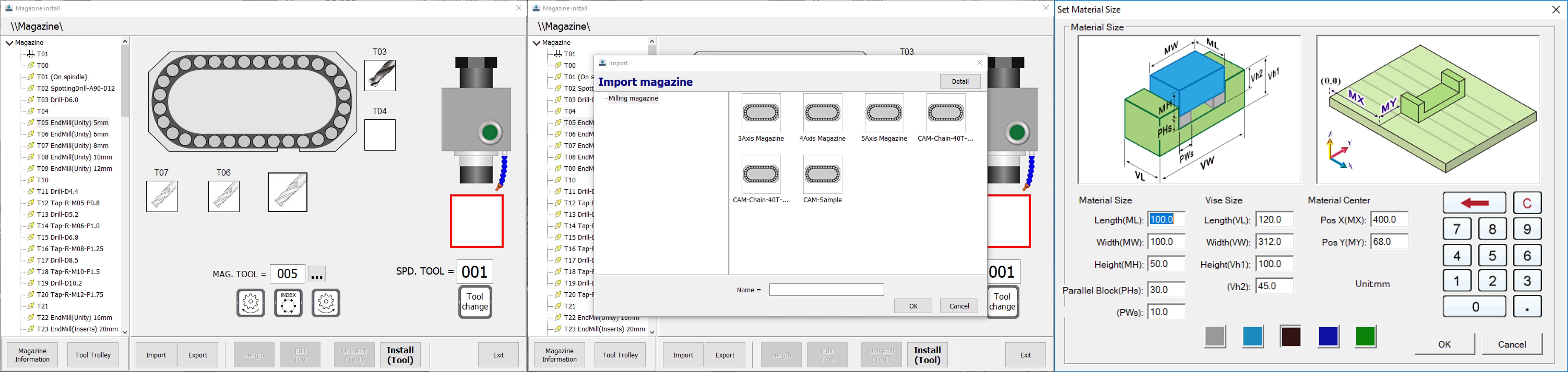
3.06 Material setting:
Rectangle workpiece dimension:
Max Length= 500mm
Max Width= 310mm
Max Height= 300mm
3.07 Magazine setting:
FaceMill, EndMill, Ball-nose EndMill, Radius Corner EndMill, Chamfer EndMill, Edge finder, Tap, Drill, Spot Drill, Thread Mill, Rough Boring, Finish Boring
3.08 Magazine install: Tool installation, modification, deletion
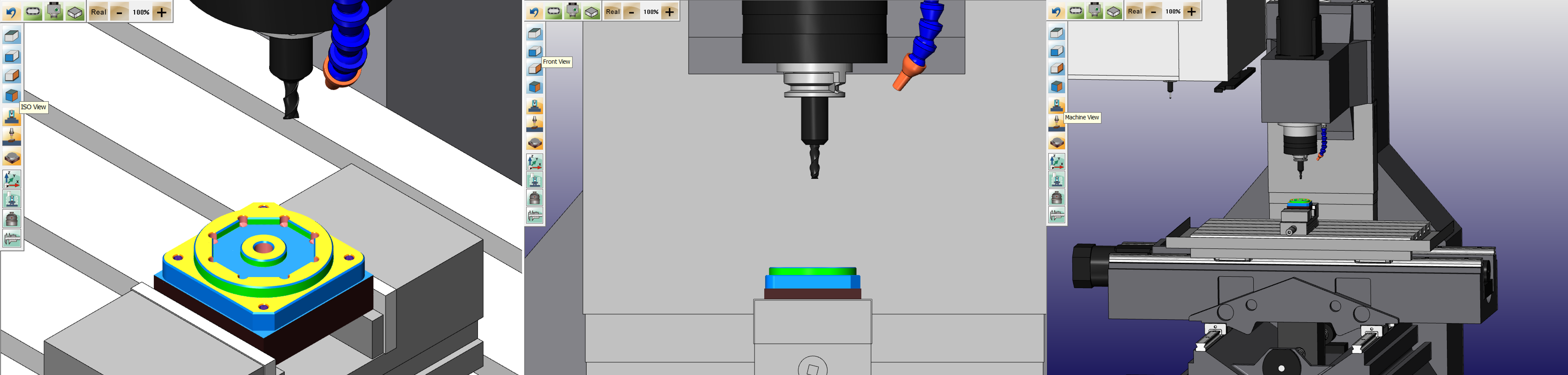
3.09 Standard view: Top (XY), Front (ZX), Side, (YZ), 3D(ISO)
3.10 Universal view Setting: Material view, Table view, Machine view
3.11 Operator view: Shift, Rotate, Zoom in/out
3.12 Offset operation: Z axis setting, Photoelectric Length setter, X Y axis setting, Photoelectric Edge finder
Standard Version Features (included)
3.21 Based on 3D solid simulation, the machine model of Vertical Milling Machining Center including: Spindle head, Vice, Z axial gauge, Tool, Auto Tool Changer ATC
3.22 Emulated design including coolant fluid, chips spattering while cut the workpiece, audio, (tool movement, cutting, spindle rotation, alarm)
3.23 Collision detection: tool and material, vice, bed
3.24 Simulation Speed Adjustment: 50%, 100%, 250%, 500%
3.25 Workpiece measurement function: Length, Width, Height, Linear distance
3.26 Quick defaulting
3.27 CNC Program Import/Export
Professional Version Additional Features
3.31 Based on 3D solid simulation, the machine model of Vertical Milling Machining Center including: Machine bed, metal shell, auto-door, spindle head, vice, Z axial gauge, tool, Auto Tool Changer
3.32 Machine case display/hide
3.33 Program zero point display according to different tool offset position
3.34 Save and import overall configuration to completely save and resume the settings status as a reference of examination and correction
3.34 Workpiece and material: save and load in (format: STL)
3.35 Tool setting: add, modify, delete, tool data import/export
3.36 Magazine Install: Import/Export, Common Magazine
3.37 Simulation Speed Adjustment: 10%, 50%, 100%, 160%, 250%, 500%, 900%, 990%, MAX
3.38 Limit the simulation speed within the range of 500% to help students with their program checking and execution
3.39 Workpiece setting: Workpiece color, heel block height, Vice dimension
3.40 Workpiece dimension measurement: angle (Absolute, counter angle), arc(three points)
3.41 Collision detection:
Tool and material, vice, bed, collision detection
Spindle and material, vice, bed, collision detection
3.42 Equipped with produce status monitoring system
3.43 The Alarm displays if the safety door is open during simulation
4 CNC Machine Simulation for Milling
4.01 The execution of program simulation including 3 axis synchro
4.02 G Code function
(1) Interpolation: G00 G01 G02 G03
(2) Dwell: G04
(3) Plane Selection: G17 G18 G19
(4) Tool Radius Compensation: G40 G41 G42 G43 G49
(5) Inch/Metric Conversion: G20 G21
(6) Workpiece dimension, Absolute/Incremental positioning: G90 G91
(7) Reference Position Return: G28 G30
(8) Feed and Speed: G94 G95 G96 G97
(9) Work coordinate: G52, G53, G54, G55, G56, G57, G58, G59
(10) Canned cycle for drilling: G73, G81, G82, G83
(11) Canned cycle for tapping: G74, G84
(12) Canned cycle for boring: G76, G85, G86, G87, G88, G89
(13) Return to the initial plane after the canned cycle G98, Return to the R-plane after the canned cycle G99
4.03 M Code auxiliary function
(M00) Program stop, (M03) Spindle forward, (M98) Subprogram call
(M01) Optional stop, (M04) Spindle reversal, (M99) Subprogram end
(M02) Program end, (M05) Spindle stop,
(M30) program end & Rewind
Standard Version Features (included)
4.21 G Code function:
(14) Support G01 Chamfer C and Corner R
(15) Omit the number sequence with decimal point (parameter)
4.22 M Code auxiliary function
(M08) Coolant fluid on (M09) Coolant fluid off
Professional Version Additional Features
4.31 G Code function:
(16)Programmable temporary Work Offset : G92
4.32 MACRO function
(1) Variable – partial variable
(2) Algorithm command –
addition +, subtraction -, multiplication x, division /
SIN, COS, TAN, SQRT square value, ABS Absolute value
(3) Condition judgement – EQ equal, NE not equal, GT greater than, LT less than, GE greater than or equal to, LE less than or equal to
(4) Divergent control –
(a) Unconditional GOTO n
(b) Conditional IF [conditional] GOTO n
(c) Repetitive execution WHILE [conditional] DO m