Commodity Number :
353-161-522-040
Commodity Name :
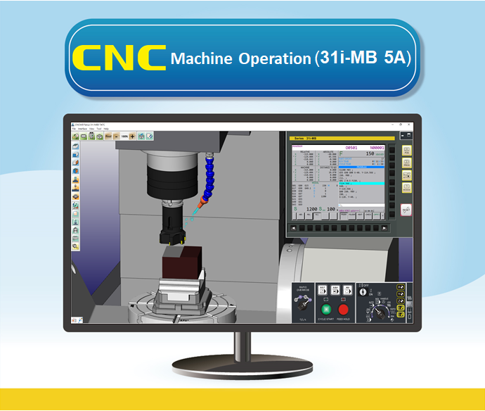
VM Fanuc 31i-MB-5A(TATC)(TBTC) 2022 Professional Version
Commodity Introduction :
Realistic CNC Controller Function Panel, Modularized Machine Operation Panel, and Machine Simulation. Excellent tool for CNC controller recognition and practicing tool offset.
Use Version :
Subscription Plan:
Commodity Price :
Product Specifications
1 CNC Controller Function
1.01 CNC Controller Simulation Fanuc 31i-MB 5A (TATC)
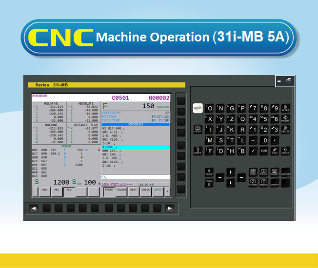
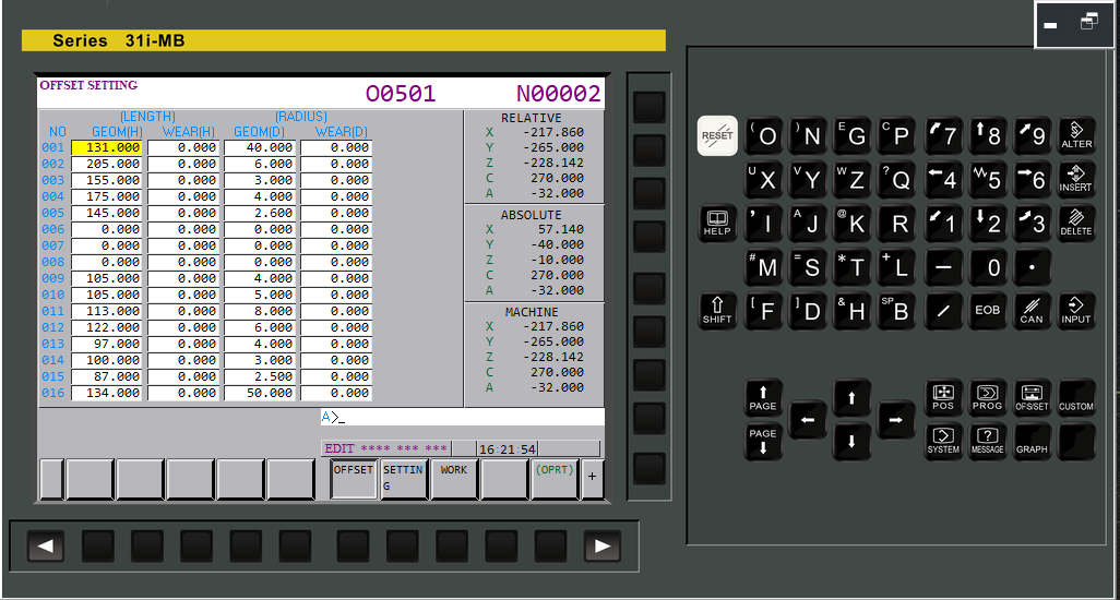
1.02 The Operation Panel Function is the complete emulation based on the actual CNC machine operation panel
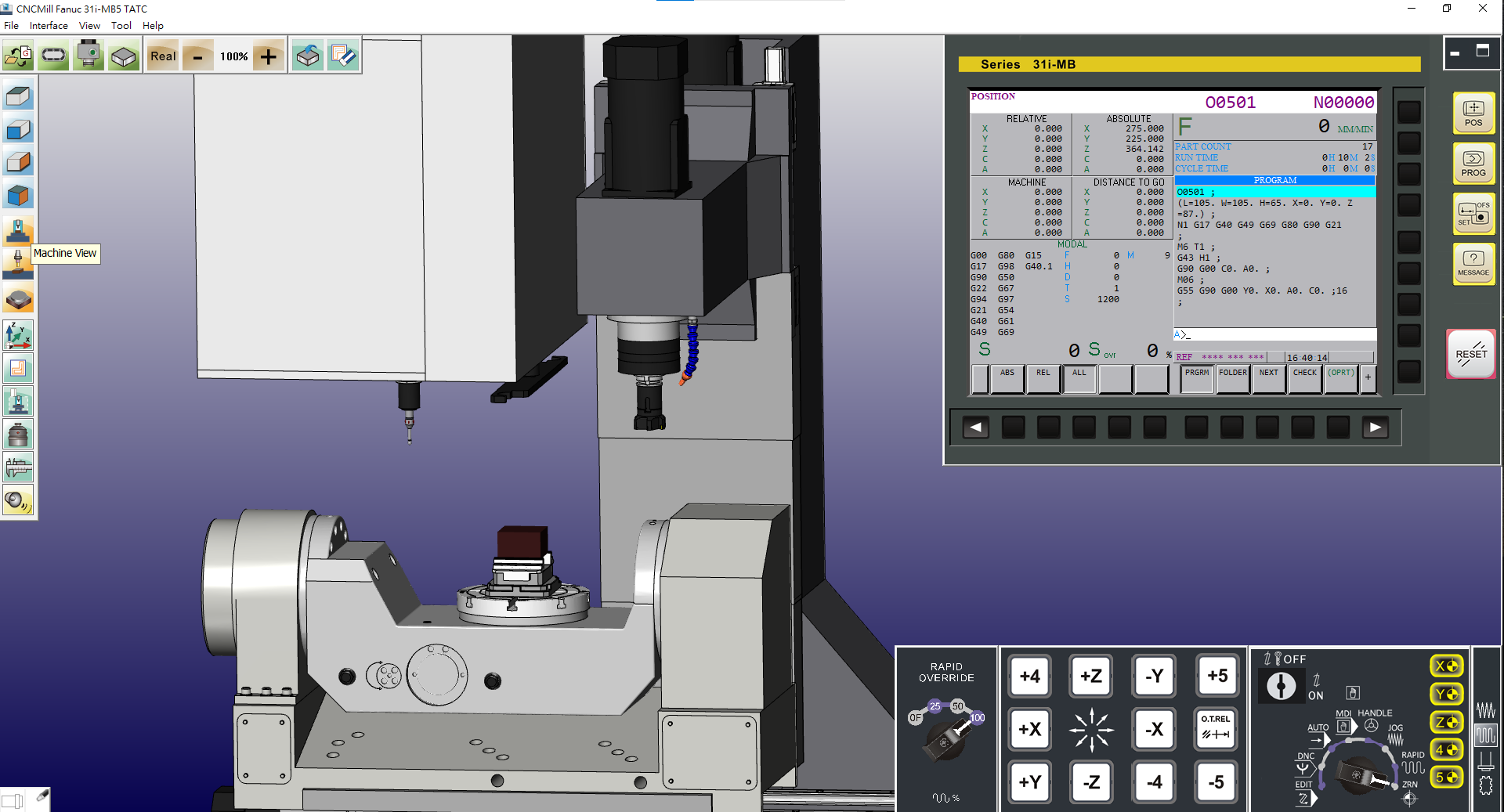
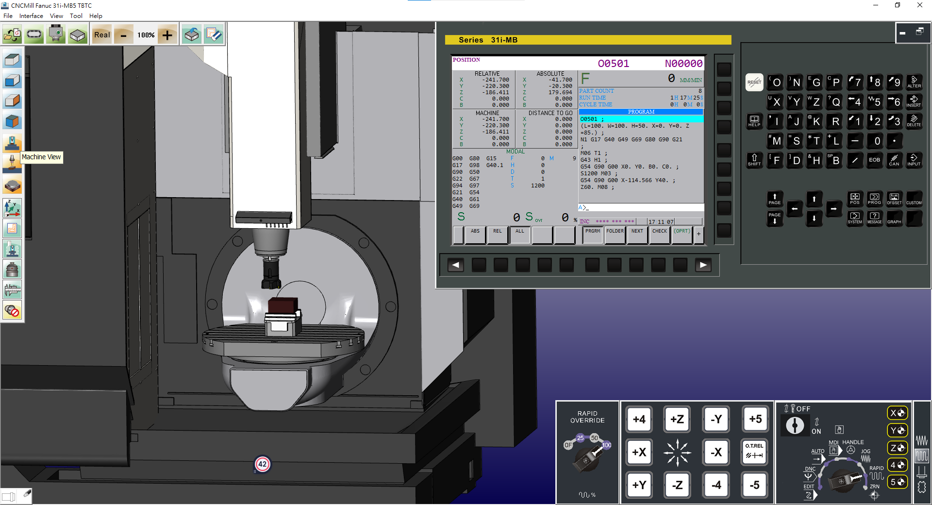
(1) Position Display [POS]: machine coordinate, absolute coordinate, relative coordinate
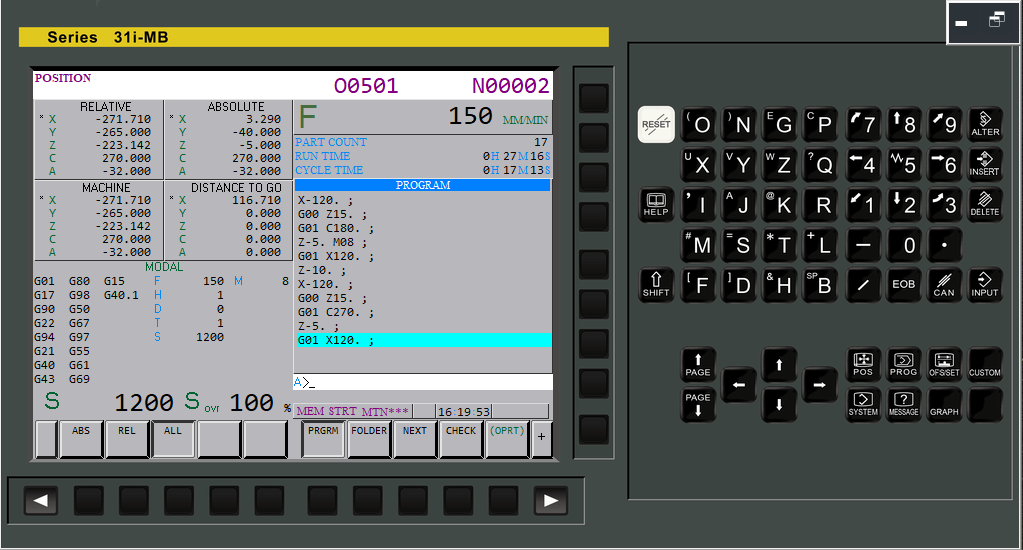
(2) Program function[PROG]:
(a) Automatic mode [AUTO]: Program content display, check, current block, next block
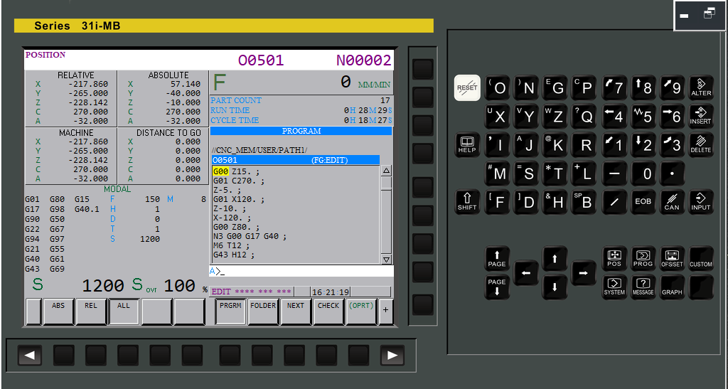
(b) Program Edit [EDIT]: [ALTER][INSERT][DELETE], program lock
(c) Background Edit
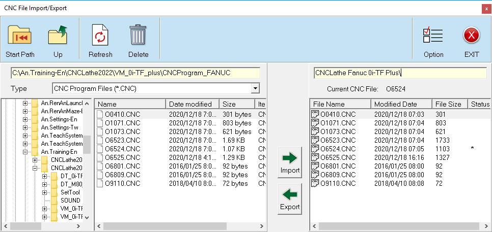
(d) Data Transfer, [F input] ,[F output]
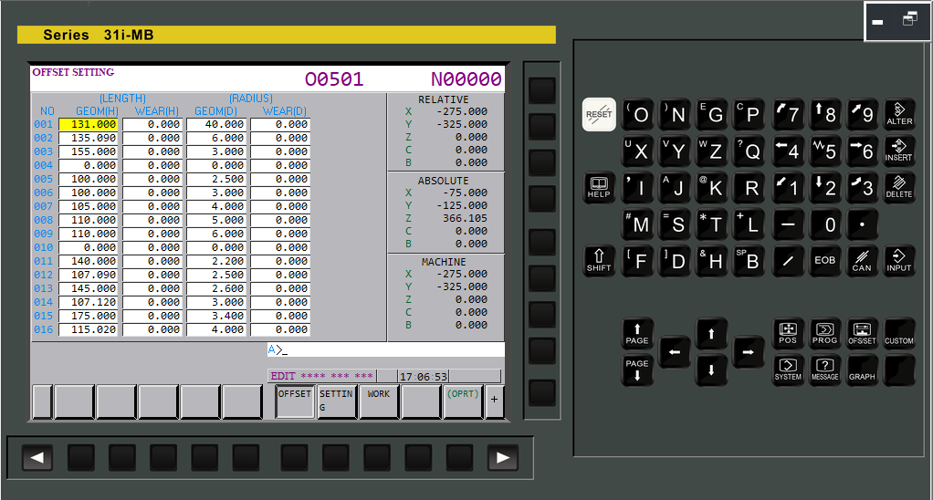
(3) Tool compensation[OFS/SET]: work shift, coordinate system, tool geometry, tool wear, MACRO, Metric/Inch mode setting
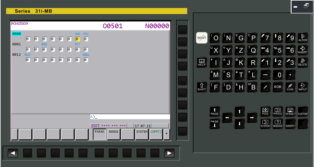
(4) System parameters [SYSTEM]: transmission, machine, edit

(5) Alphabetic and Numeric keys, [INPUT], [RESET], [CANCEL]
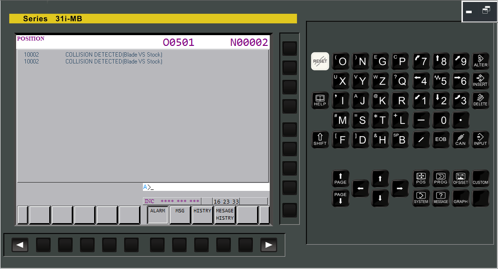
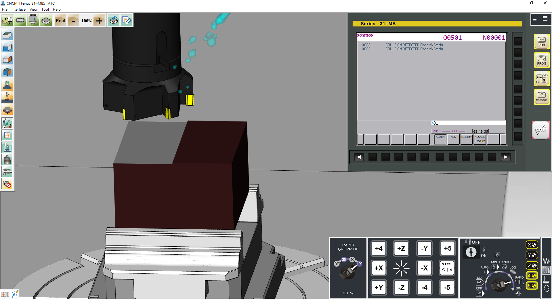
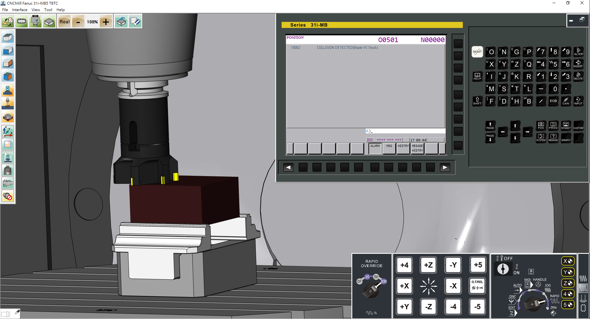
1.03 Alarm display
The alarm codes show the same codes as in the machine
(1) E.g.: X axis is over travel, the alarm code indicates:
”500 OVER TRAVEL:+X”
To clear the alarm , move X axis to the proper position and press [RESET] to clear the alarm
(2) E.g.: 1211 EMG ESTOP, pull up the emergency button to clear alarm
(3) System records the time and the error codes whenever the alarm message is displayed
1.04 To transmit the program by using RJ45 interface information transmission function
Professional Version Additional Features
1.21 Operation Panel Function
(6) Graphic function: Display path simulation, Drawing Parameter [PARAM],
Path Drawing: Drawing from the head of the program [START], Executes the program for drawing and stops temporarily on a block-by-block [1BLOCK], [REWIND], [ERASE], [STOP]
Moving the graphic range,
Changing the graphic coordinate system,
Rotating the graphic coordinate system
2 CNC Machine Operation Panel
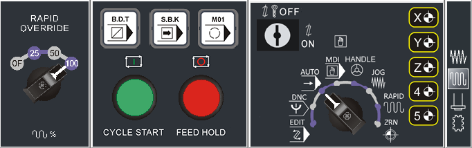
2.01 Mode Select Function
(1) [EDIT] Program edit mode – Edit program content
(2) [AUTO] Auto execution mode – Program executes automatically
(3) [MDI] Manual Data Input – For parameter settings and temporary input program
(4) [HANDLE] Handle mode – Using handwheel move and adjustment position
(5) [JOG] Cutting feed mode – Using axis key to feed
(6) [RAPID] Rapid mode – Using axis key to move rapidly
(7) [ZRN] Zero Point Return – X, Z axis return to Machine Home Position
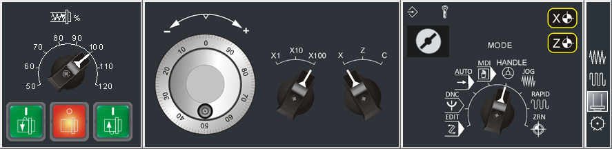
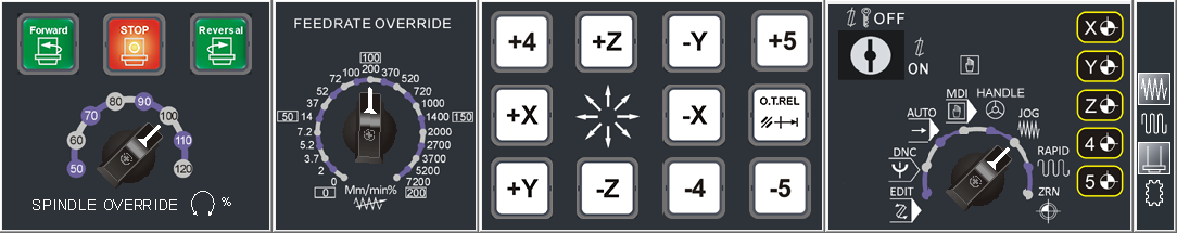
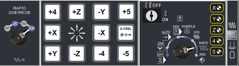
2.02 Rapid Speed adjustment button, Feed speed adjustment button, Spindle speed adjustment button
2.03 Optional block skip [B.D.T], Single block execution [S.B.K], Optional stop [M01], Start [CYCLE START], Stop [FEED HOLD]
2.04 Spindle forward, Spindle stop, Spindle reversal
2.05 Program lock, Emergency stop, Tool change button, Coolant
2.06 Axis movement buttons: [+X]、[-X]、[+Y]、[-Y]、[+Z]、[-Z]、[+4]、[-4]、[+5]、[-5], Reset button, axis return signal
2.07 manual handle rate button, manual handle axis button
Professional Version Additional Features
2.08 Working light button, Safety door open/ close
3 CNC Machine Simulation for Turning
3.01 Based on 3D physical construction, the machine model of Vertical
5 axis Milling including: Single spindle and chuck, Z axis tool setter, tool, Automatic tool changer ATC
Distance: X axis 840 mm 、Y axis 510 mm 、Z axis 585 mm
Rapid: X axis 18 m/min、Y axis 18 m/min、Z axis 18 m/min
Axis 24 rpm 、C axis 24 rpm
Max Feedrate: X axis 6 m/min、Y axis 6 m/min、Z axis 6 m/min
A axis 24 rpm 、C axis 24 rpm
3.02 Simulate whole CNC machine with physical machine controlling panel and dynamic interactive simulation
3.03 Collision detection function: tool and material. If the tool isn’t rotating, the contact between the tool and the material will be considered a collision
3.04 Simulation Speed Adjustment: 50%、100%、250%、500%
3.05 Worktable: Cradle type rotating table (A axis + C axis)
3.06 Audio on/off, system volume adjustment
3.07 Workpiece material setting,
(1) Cuboid material: Length,Max Length = 230 mm
Width, max = 200 mm
Height, max = 200 mm
(2) Cylinder material: diameter, maximum = 120 mm
Length,Max Length = 250 mm
Elongation, maximum = 200 mm
(3) Workpiece Position
3.08 Turret setting: Tool install, modify, delete

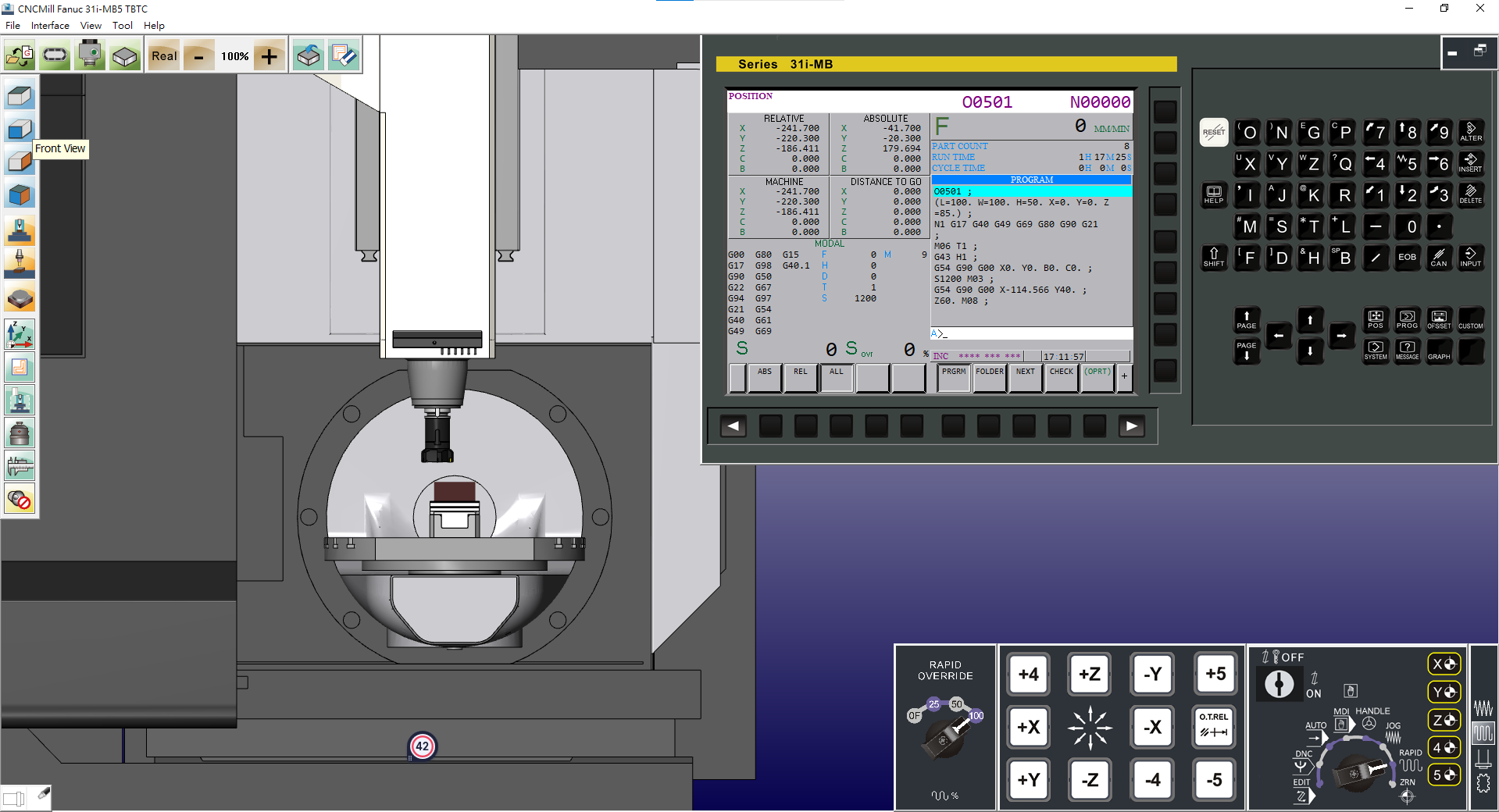
3.09 Standard view : Top (XY), Front (ZX), Side, (YZ), 3-Dimension (ISO)
3.10 Common zoom view: Material view, Table view, Machine view
3.11 Free operation view: Shift, Rotate, Zoom in/out

Standard Version Features (included)
3.21 Based on 3D physical construction, the machine model of Vertical
5 axis Milling including: Single spindle and chuck, Z axis tool setter, tool, Automatic tool changer ATC
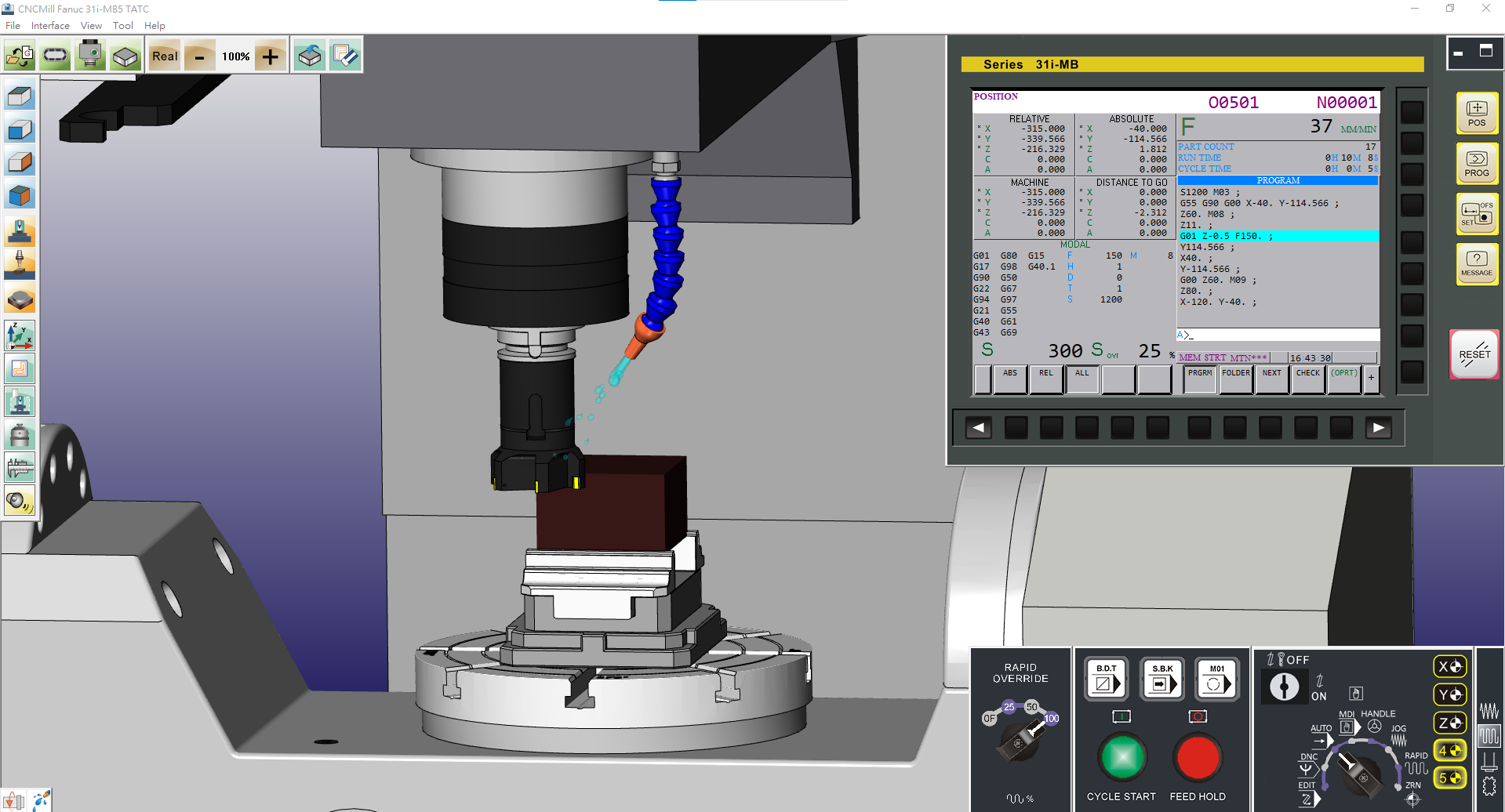
3.22 Simulated design including coolant fluid, cutting the workpiece until chips spattering, audio (tool movement, cutting sound effect, spindle rotation, alarm)
3.23 Collision detection function: tool and material, jaw, tailstock, collision detection
3.24 Workpiece size measurement function: length, width, height, straight
line distance, Angle measurement (absolute angle, two-sided angle),
Arc measurement (three-point circle)
3.25 Install/remove spindle tool
3.26 Quick reset to Factory Setting
3.27 CNC Program import/export function
4 CNC Machine Simulation for Turning
4.01 G Code function
(1) Interpolation: G00 G01 G02 G03
(2) Dwell: G04
(3) Plane Selection: G17 G18 G19
(4) Workpiece dimension: Input in inch/mm: G20 G21
(5) Return to reference position: G28 G30
(6) Feed per minute/ revolution: G98 G99, Constant surface speed control: G96 G97
(7) Workpiece Coordinate: G54, G55, G56, G57, G58, G59
4.02 M Code auxiliary function
(M00) Program stop, (M03) Spindle forward,
(M01) Optional stop, (M04) Spindle reversal,
(M02) End of program, (M05) Spindle stop,
(M98) Calling of Subprogram
(M99) End of Subprogram
(M30) end of program
Standard Version Features (included)
4.21 G Code function
(9) Support G01 axis right angle of auto Chamfering/ corner R
(10) Cutting cycle G71, G72, G73, G74, G75, G76, G90, G92, G94
(11) Canned cycle for drilling & tapping: G80, G83, G84, G85
(12) Coordinate system setting or max spindle speed clamp: G50
(13) Chamfer command settings using comma (parameter)
(14) Omitting the use of decimal point of address (parameter)
(15) Using G Code group setting (parameter)
(16) Tool Radius Compensation: G40 G41 G42
4.22 M Code auxiliary function
(M08) Coolant fluid on (M09) Coolant fluid off
Professional Version Additional Features
4.31 G Code function:
(17) Support G01 Angle A command
(18) Support G01with auto Chamfer and Radius of any included angle
(19) Complete support for G71 Canned CycleII multiple stages rough cutting
(20) MACRO mode call: G66, G67
4.32 MACRO program function
(1) Program variable – partial variable
(2) Arithmetic command –
addition +, subtraction -, multiplication x, division /
SIN, COS, TAN, SQRT square value, ABS Absolute value
(3) Logic Operations – EQ equal to, NE not equal to, GT greater than, LT less than, GE greater than or equal to, LE less than or equal to
(4) Conditional Branches –
(a) Unconditional branches GOTO n
(b) Conditional branches IF [conditional] GOTO n
(c) Repetitive execution WHILE [conditional] DO m
Product Specifications
1 CNC Controller Function
1.01 CNC Controller Simulation Fanuc 31i-MB 5A (TBTC)
1.02 The Operation Panel Function is the complete emulation based on the actual CNC machine operation panel
(1) Position Display [POS]: machine coordinate, absolute coordinate, relative coordinate

(2) Program function[PROG]:
(a) Auto [AUTO] : program content display, check
(b) Program Edit [EDIT]: [ALTER][INSERT][DELETE], program lo
(c) Program Transmission, [F input], [F output]

(3) Tool compensation[OFS/SET]: work shift, coordinate system, tool geometry, tool wear, MACRO, Metric/Inch mode setting
(4) System parameters [SYSTEM]: transmission, machine, edit
(5) Alphabetic and Numeric keys, [INPUT], [RESET], [CANCEL]
1.03 Alarm display
The alarm codes show the same codes as in the machine
(1) E.g.: X axis is over travel, the alarm code indicates:
”500 OVER TRAVEL:+X”
To clear the alarm , move X axis to the proper position and press [RESET] to clear the alarm

(2) E.g.: 1211 EMG ESTOP, pull up the emergency button to clear alarm
(3) System records the time and the error codes whenever the alarm message is displayed
1.04 To transmit the program by using RJ45 interface information transmission function
Professional Version Additional Features
1.21 Operation Panel Function
(6) Graphic function: Display path simulation, Drawing Parameter [PARAM],
Path Drawing: Drawing from the head of the program [START], Executes the program for drawing and stops temporarily on a block-by-block [1BLOCK], [REWIND], [ERASE], [STOP]
Moving the graphic range,
Changing the graphic coordinate system,
Rotating the graphic coordinate system
2 CNC Machine Operation Panel
2.01 Mode Select Function
(1) [EDIT] Program edit mode – Edit program content
(2) [AUTO] Auto execution mode – Program executes automatically
(3) [MDI] Manual Data Input – For parameter settings and temporary input program
(4) [HANDLE] Handle mode – Using handwheel move and adjustment position
(5) [JOG] Cutting feed mode – Using axis key to feed
(6) [RAPID] Rapid mode – Using axis key to move rapidly
(7) [ZRN] Zero Point Return – X, Z axis return to Machine Home Position
2.02 Rapid Speed adjustment button, Feed speed adjustment button, Spindle speed adjustment button
2.03 Optional block skip [B.D.T], Single block execution [S.B.K], Optional stop [M01], Start [CYCLE START], Stop [FEED HOLD]
2.04 Spindle forward, Spindle stop, Spindle reversal
2.05 Program lock, Emergency stop, Tool change button, Coolant
2.06 Axis movement buttons: [+X]、[-X]、[+Y]、[-Y]、[+Z]、[-Z]、[+4]、[-4]、[+5]、[-5], Reset button, axis return signal
2.07 manual handle rate button, manual handle axis button
Professional Version Additional Features
2.08 Working light button, Safety door open/ close
3 CNC Machine Simulation for Turning
3.01 Based on 3D physical construction, the machine model of Vertical
5 axis Milling including: Single spindle and chuck, Z axis tool setter, tool, Automatic tool changer ATC
Distance: X axis 840 mm 、Y axis 510 mm 、Z axis 585 mm
Rapid: X axis 18 m/min、Y axis 18 m/min、Z axis 18 m/min
Axis 24 rpm 、C axis 24 rpm
Max Feedrate: X axis 6 m/min、Y axis 6 m/min、Z axis 6 m/min
A axis 24 rpm 、C axis 24 rpm
3.02 Simulate whole CNC machine with physical machine controlling panel and dynamic interactive simulation
3.03 Collision detection function: tool and material. If the tool isn’t rotating, the contact between the tool and the material will be considered a collision
3.04 Simulation Speed Adjustment: 50%、100%、250%、500%
3.05 Worktable: Cradle type rotating table (B axis + C axis)
3.06 Audio on/off, system volume adjustment
3.07 Workpiece material setting,
(1) Cuboid material: Length,Max Length = 230 mm
Width, max = 200 mm
Height, max = 200 mm
(2) Cylinder material: diameter, maximum = 120 mm
Length,Max Length = 250 mm
Elongation, maximum = 200 mm
(3) Workpiece Position
3.08 Turret setting: Tool install, modify, delete
3.09 Standard view : Top (XY), Front (ZX), Side, (YZ), 3-Dimension (ISO)
3.10 Common zoom view: Material view, Table view, Machine view
3.11 Free operation view: Shift, Rotate, Zoom in/out
Standard Version Features (included)
3.21 Based on 3D physical construction, the machine model of Vertical
5 axis Milling including: Single spindle and chuck, Z axis tool setter, tool, Automatic tool changer ATC

3.22 Simulated design including coolant fluid, cutting the workpiece until chips spattering, audio (tool movement, cutting sound effect, spindle rotation, alarm)
3.23 Collision detection function: tool and material, jaw, tailstock, collision detection
3.24 Workpiece size measurement function: length, width, height, straight
line distance, Angle measurement (absolute angle, two-sided angle),
Arc measurement (three-point circle)
3.25 Install/remove spindle tool
3.26 Quick reset to Factory Setting
3.27 CNC Program import/export function
4 CNC Machine Simulation for Turning
4.01 G Code function
(1) Interpolation: G00 G01 G02 G03
(2) Dwell: G04
(3) Plane Selection: G17 G18 G19
(4) Workpiece dimension: Input in inch/mm: G20 G21
(5) Workpiece dimension: Absolute / Incremental: G90 G91
(5) Return to reference position: G28 G30
(6) Feed rate command: G94 G95
(7) Constant surface speed control: G96、G97
(8) Maximum rotate speed rate: G92
(9) Workpiece Coordinate: G52、G53、G54、G54.1、
G55、G56、G57、G58、G59
4.02 M Code auxiliary function
(M00) Program stop, (M03) Spindle forward,
(M01) Optional stop, (M04) Spindle reversal,
(M02) End of program, (M05) Spindle stop,
(M30) End of program & Return、
(M06) Automatic tool change
(M98) Calling of Subprogram
(M99) End of Subprogram
Standard Version Features (included)
4.21 G Code function
(21)Support G01 Angle A command with auto Chamfer and Radius
of any included angle
(22) MACRO mode call: G65、G66、G67
(23) Travel Limit inspection: G22、G23
(24) Data Input: G10
(25) Rotate Coordinate: G68、G69
(26) Automatic tool length measurement: G37
(27) Programmable temporary Work Offset: G92
(28) Polar coordinates command: G15、G16
(29) Scale command: G50、G51
(30) Rotated Tool Center Point (RTCP): G43.4、G43.5
(31) Tool axial direction control: G53.1、G53.6
(32) Titled working plane indexing: G68.2、G68.3、G68.4
4.22 4.23 MACRO program function
(1) Program variable – partial variable
(2) Arithmetic command : addition +, subtraction -,
multiplication x, division /SIN, COS, TAN, SQRT square value, ABS Absolute value
(3) Logic Operations : EQ equal to, NE not equal to, GT greater
then, LT less than, GE greater than or equal to, LE less than or
equal to
(4) Conditional Branches :
(a) Unconditional branches GOTO n
(b) Conditional branches IF [conditional] GOTO n
(c) Repetitive execution WHILE [conditional] DO m