Commodity Number :
362-511-522-040
Commodity Name :
VM Siemens 840D-5A(TATC) 2022 Professional Version
Commodity Introduction :
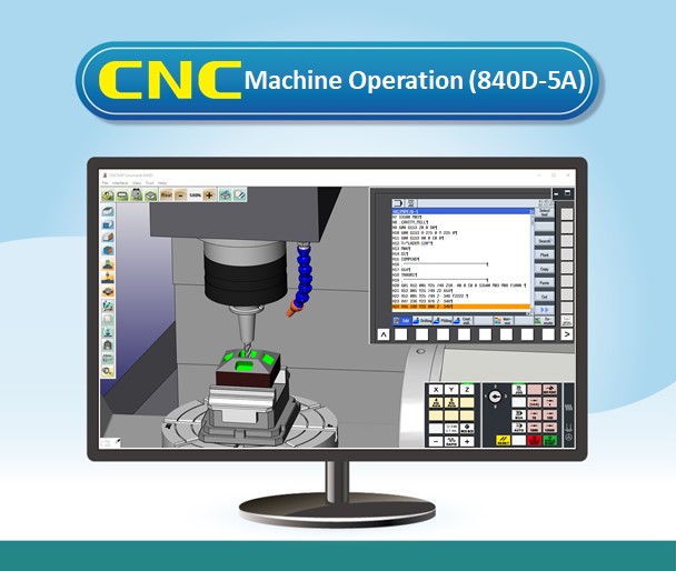
Realistic CNC Controller Function Panel, Modularized Machine Operation Panel, and Machine Simulation. Excellent tool for CNC controller recognition and practicing tool offset.
Use Version :
Subscription Plan:
Commodity Price :
Product Specifications
1 CNC Controller Operation Panel Function
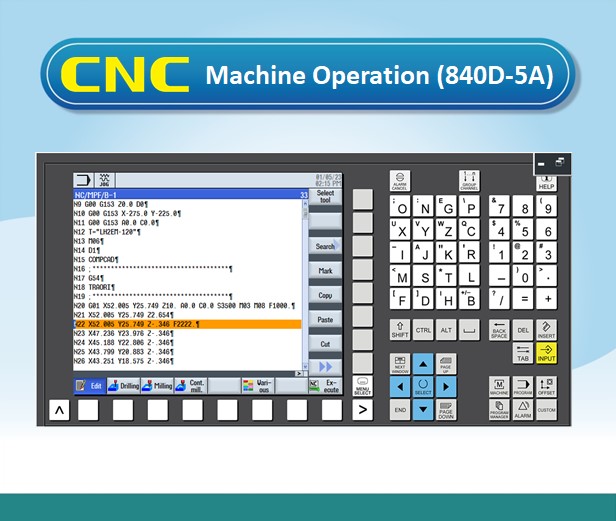
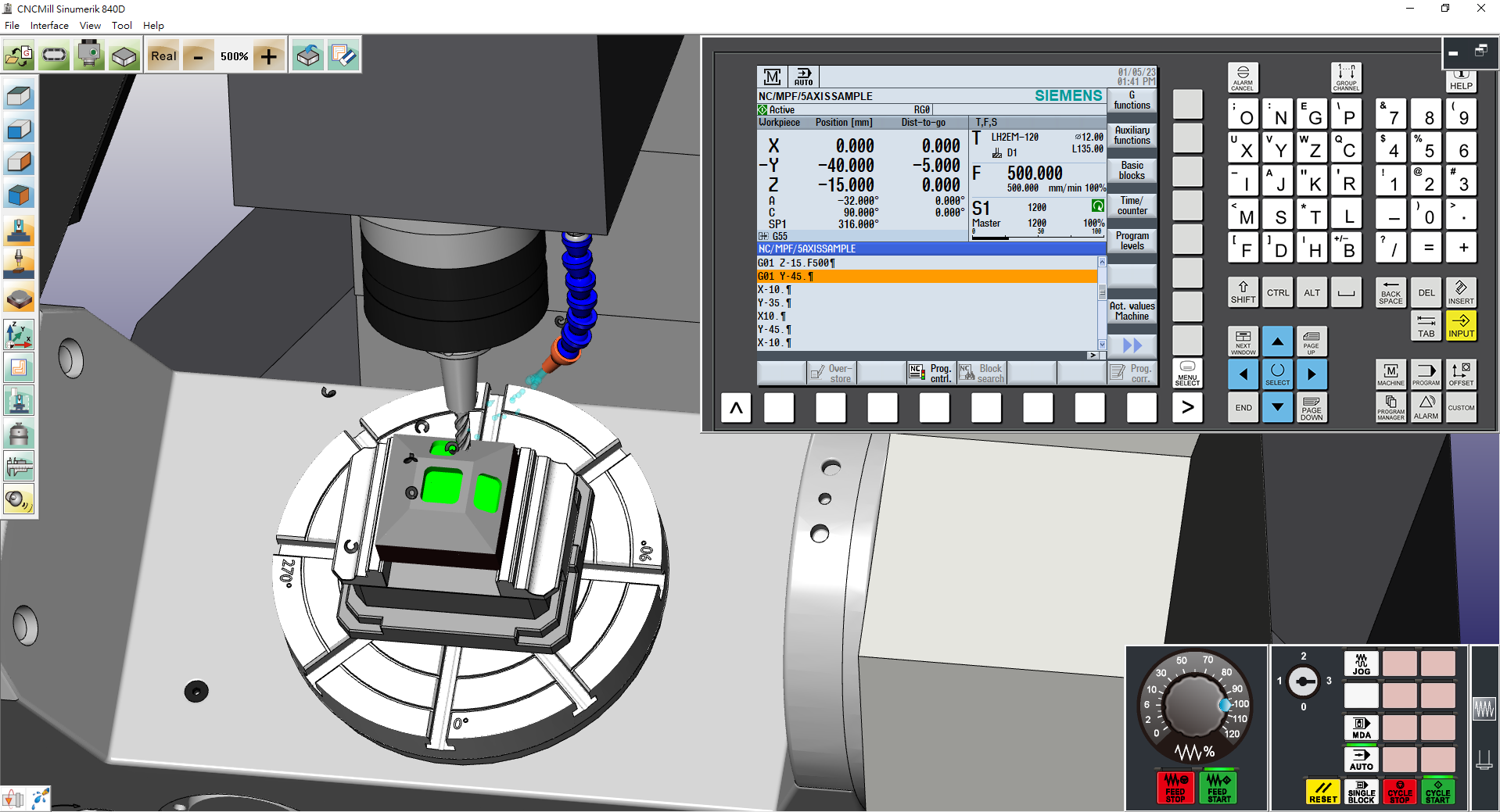
1.01 CNC Controller Simulation SINUMERIK 840D 5 Axis
1.02 The Operation Panel Function is the complete emulation based on the actual SINUMERIK 840D sl CNC machine operation
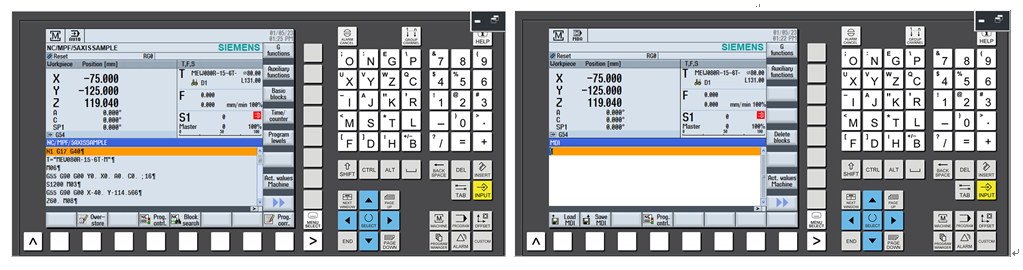
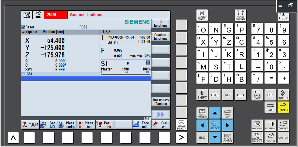
(1)[Machine] Machining operation: display machine coordinate, absolute coordinate and machining status
a.(AUTO) Overstore, program control, block search, settings
b.(MDA) Load MDA, save MDA, program control, settings
c.(JOG) TSM, Set W0, position, face mill setting,
tilting function, settings, changeover inch
Measure workpiece:Probe calibration, edge, 2 edges, round spigot
Measure tool: length manual, diameter manual, fixed point calibration
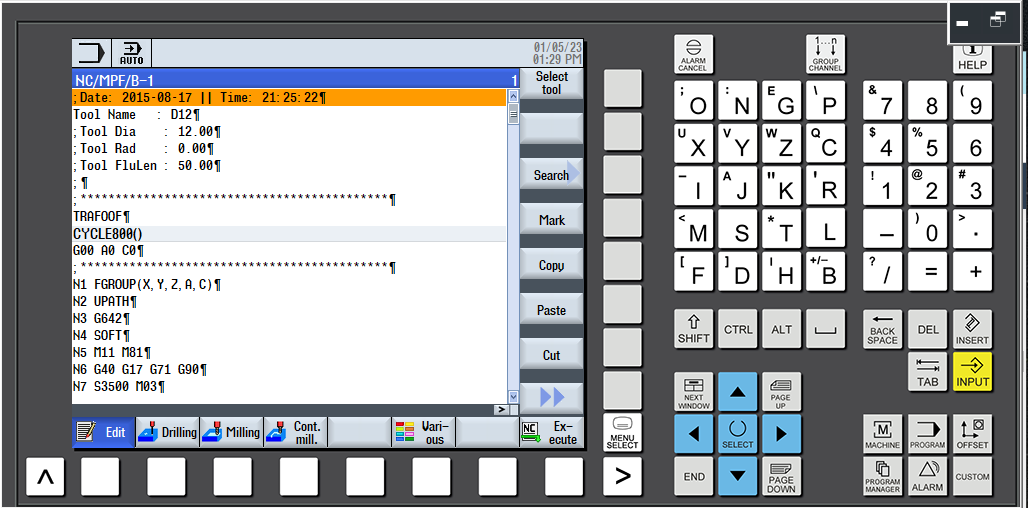
(2) [PROGRAM] Program editing:
(a) Function key (edit):
Select tool, search, mark, copy, paste, cut, renumbering, settings, exit
(b) Cycle command edit (drilling):
Centering, Drilling, reaming, deep hole drilling, boring, tapping, thread, positions, position repetition
(c) Cycle command edit (milling):
Face milling
Pocket: Rectangular Pocket, Circular Pocket
Spigot: Rectangular spigot, Circular spigot, Multi-edge spigot
Groove: Longitudinal groove, Circumferential groove, Open slot, Elongated slot
Thread milling
(d) Cycle command edit(contour milling):
Create new contour, Contour call, Path milling, Centering, Rough drill,
Pocket, Residual material contour pocket,
Spigot, Residual material contour spigot
(e) Cycle command edit(other):
Blank, Table swiveling (cycle800), High speed setting, Sub-program
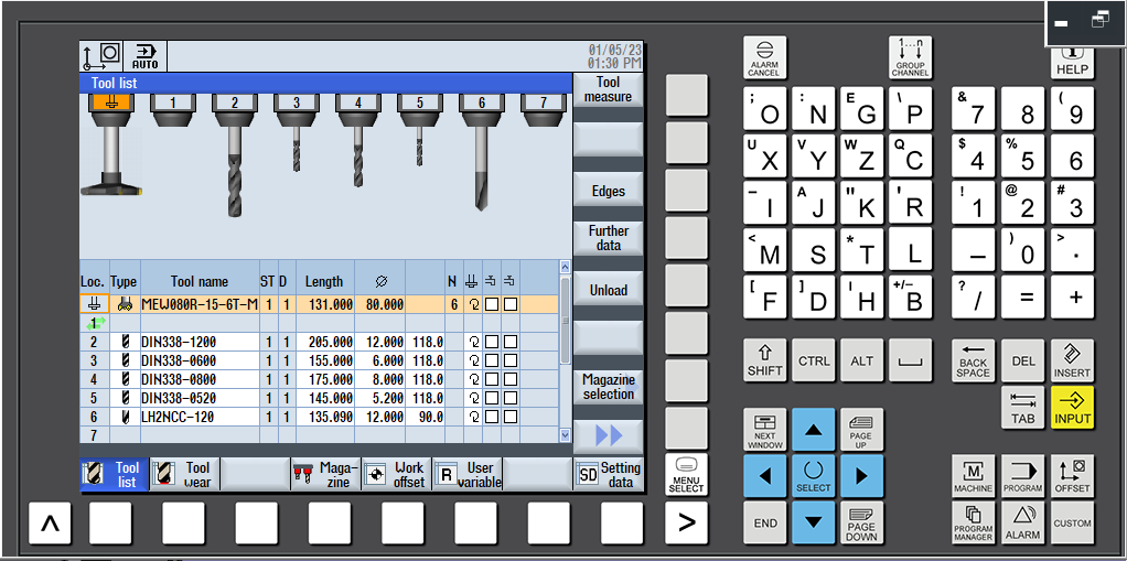
(3) [OFFSET] Tool offset:
(a) Tool offset (Geometry): Tool basic information setting, tool measure, edge, unload, magazine selection, sort
(b) Tool offset (Wear) : Sort
(c) Coordinates offset G54-G57: Set W0, Active, Overview, Base,
G54 G55 G56 G57, Details
(d) Working area limitation
(4) [PROGRAM MANNGER] Program: Execute, New, Open, Mark, Copy, Paste, Cut, Search, Properties, Delete
(5) [ALARM] Alarm: Alarm list, Alarm log
2 CNC Machine Operation Panel
2.01 Mode Select Button Function
(1) [AUTO] Auto execution mode - Program executes automatically
(2) [MDA] Manual Data Input - For parameter settings and temporary input program
(3) [JOG] Cutting feed mode - Using axis key to feed
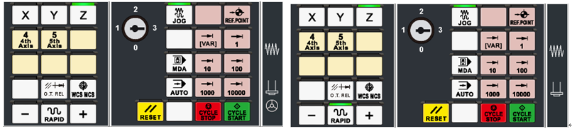
(4) [RAPID] Rapid mode - Using axis key to move rapidly
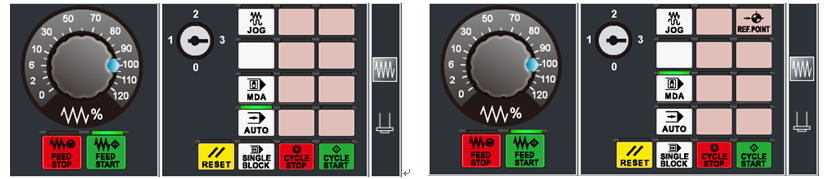
2.02 Rapid override
2.03 [CYCLESTART], [CYCLESTOP], [SINGLE BLOCK], [RESET]
2.04 Spindle forward, Spindle stop, Spindle reversal
2.05 Program lock, Emergency stop, Tool change button, Coolant, Safety door open/ close
2.06 Axis movement buttons [X], [Y], [Z], [4TH AXIS], [5TH AXIS], positive[+], negative[-], [RAPID], Reset button, axis return signal [REF.POINT]
2.07 Manual handle button[MPG], Physical manual handle, MPG feedrate, MPG axis button
3 CNC Milling Machine Simulation
3.01 Based on 3D physical construction, the machine model of 5 Axis Vertical Machining Center includes Machine bed, Vise, Z tool setter,Tool, Auto Tool Change ATC
Travel: X axis 650 mm, Y axis 650 mm, Z axis 550 mm
Rapid: X axis 18 m/min, Y axis 18 m/min, Z axis 18 m/min
A axis 24 rpm, C axis 24 rpm
Max Cutting Feed: X axis 6 m/min, Y axis6 m/min, Z axis 6 m/min
A axis 24 rpm, C axis 24 rpm
3.02 Simulate whole CNC machine with physical machine control panel and dynamic interactive simulation
3.03 Collision detection function: tool and material. If the tool isn’t rotating, the contact between the tool and the material will be considered a collision

3.04 Simulation speed adjustment: 100%, 160%, 250%, 500%
3.05 Working Table: Trunnion type swivel table (A axis + C axis)
3.06 Workpiece setting
(1) Cubic workpiece dimension: Max Length= 230mm
Max Width= 200mm
Max Height= 200mm
(2) Cylinder workpiece dimension: Max Diameter= 120mm
Max Length= 250mm
Max Reach= 200mm
(3) Workpiece position
3.07 Milling, Magazine, Tool setting:
Face Mill Cutter, End Mill, Radius Corner Endmill, Ball-Nose Endmill,
Chamfer Endmill, Edge Finder, Spot Drill, Tap, Drill, Thread, Rough Boring,
Finish Boring Insert, High Speed Drill
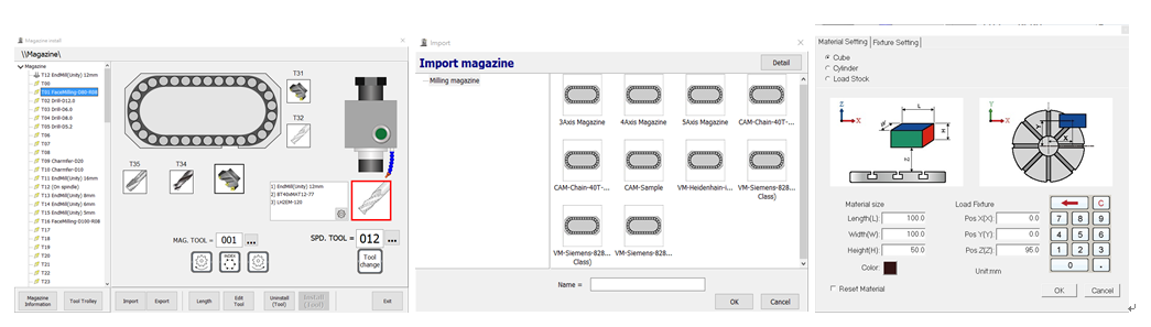
3.08 Magazine install: Tool install, modify, delete
3.09 Standard view : Top (XY), Front (ZX), Side, (YZ), 3Dimension (ISO)
3.10 Universal view setting: Material range, Machine bed range, machine range
3.11 Operator view: Shift, Rotate, Zoom in/out
3.12 Tool offset operation: Z axis setting, Photoelectric Length tool setter
X, Y axis setting, Photoelectric Edge finder
Standard Version Features (included)
3.21 Based on 3D physical construction, the machine model of 5 Axis Vertical Machining Center includes Machine bed, Spindle head, Vise, Z axial tool setter, Tool, Auto Tool Changer ATC.
3.22 Simulated design including coolant fluid, cutting the workpiece until chips spattering, audio (tool movement, cutting sound effect, spindle rotation, alarm)
3.23 Collision detection: tool and material, vise, swivel table, collision detection
3.24 Simulation Speed Adjustment: 50%, 100%, 250%, 500%
3.25 Workpiece linear measurement function: length, width, height, linear path

3.26 Quick reset to Factory Setting
3.27 CNC Program Import/Export function
Professional Version Additional Features
3.31 Based on 3D physical construction, the machine model of 5 Axis Vertical Machining Center includes Machine bed, metal shell, auto-door, spindle head, vise, Z axial tool setter, tool, Auto Tool Changer
3.32 Machine case display/hide
3.33 Program zero point display according to tool offset value
3.34 Save and import configuration to completely save and resume the settings status as a reference of examination and correction
3.35 Workpiece material: save and load in (format: STL)
3.36 Tool setting: add, modify, delete, tool data import/export
3.37 Magazine Install: Import/Export, Common Magazine
3.38 Simulation Speed Adjustment: 10%, 50%, 100%, 160%, 250%, 500%, 900%, 990%, MAX
3.39 Limit the simulation speed within the range of 500% to help students with their program check and execution
3.40 Workpiece setting: Workpiece color, block height, Vise dimension
3.41 Workpiece dimension measure:
angle measurement (Absolute, both sides angle), arc(three points circle)
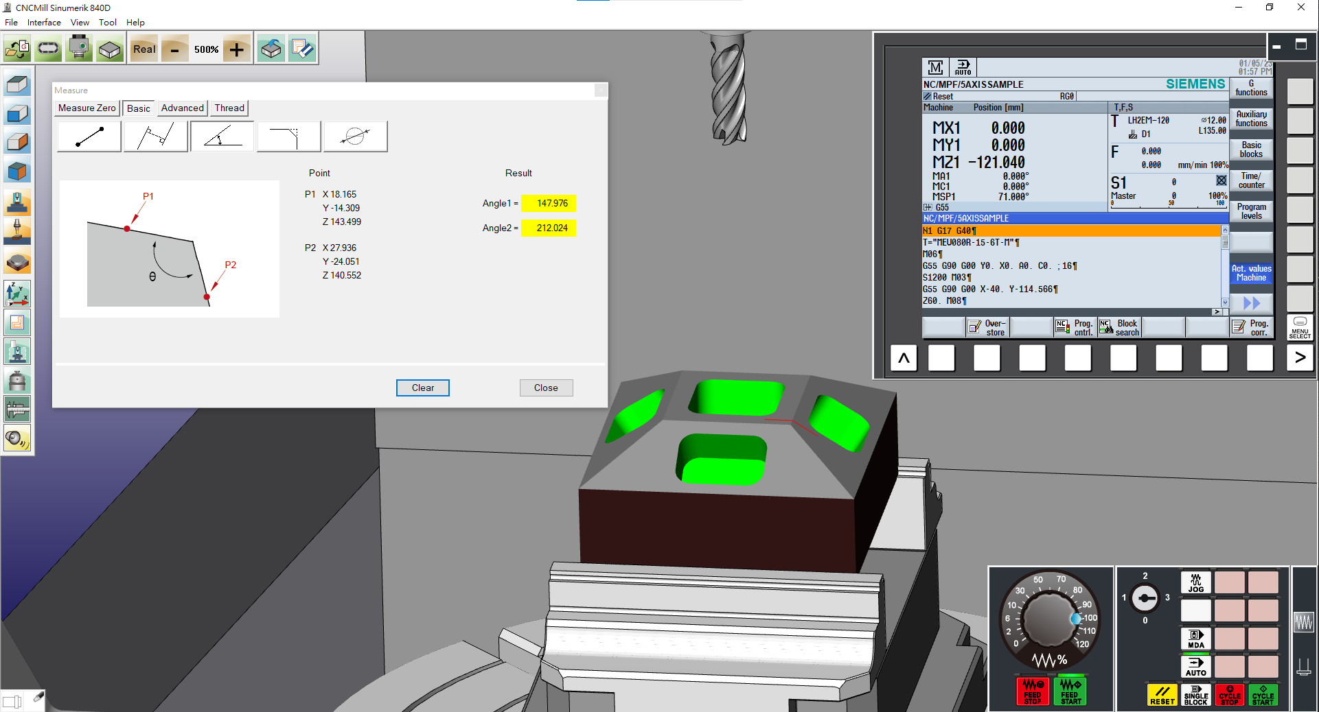
3.42 Equipped with machine produce status and immediate monitoring management system
3.43 Spindle speed and feedrate detection function:
(1) Spindle spins correctly and spindle speed is in regulated range.
(2) Feedrate in regulated range.
3.44 Tool and material collision detection function:
(1) Spindle not spinning or incorrect spinning direction and tool and material touches is regarded as collision.
(2) Non-cutting part of tool touches material is regarded as collision.
(3) Feedrate too high and over permitted range is regarded as collision.
3.45 Collision detection:
Tool and material, vise, swivel table, collision detection
Spindle and material, vise, swivel table, collision detection
CNC 5 Axis Program Simulation
3.31 Based on 3D physical construction, the machine model of 5 Axis Vertical Machining Center includes Machine bed, metal shell, auto-door, spindle head, vise, Z axial tool setter, tool, Auto Tool Changer
3.32 Machine case display/hide
3.33 Program zero point display according to tool offset value
3.34 Save and import configuration to completely save and resume the settings status as a reference of examination and correction
3.35 Workpiece material: save and load in (format: STL)
3.36 Tool setting: add, modify, delete, tool data import/export
3.37 Magazine Install: Import/Export, Common Magazine
3.38 Simulation Speed Adjustment: 10%, 50%, 100%, 160%, 250%, 500%, 900%, 990%, MAX
3.39 Limit the simulation speed within the range of 500% to help students with their program check and execution
3.40 Workpiece setting: Workpiece color, block height, Vise dimension
3.41 Workpiece dimension measure:
angle measurement (Absolute, both sides angle), arc(three points circle)
3.42 Equipped with machine produce status and immediate monitoring management system
3.43 Spindle speed and feedrate detection function:
(1) Spindle spins correctly and spindle speed is in regulated range.
(2) Feedrate in regulated range.
3.44 Tool and material collision detection function:
(1) Spindle not spinning or incorrect spinning direction and tool and material touches is regarded as collision.
(2) Non-cutting part of tool touches material is regarded as collision.
(3) Feedrate too high and over permitted range is regarded as collision.
3.45 Collision detection:
Tool and material, vise, swivel table, collision detection
Spindle and material, vise, swivel table, collision detection
CNC 5 Axis Program Simulation
4.01 Program executes cutting simulation includes 3+2 Axis
4.02 G Code function
(1) Interpolation: G00 G01 G02 G03
(2) Dwell: G04
(3) Plane Selection: G17 G18 G19
(4) Tool Radius Compensation Command: G40 G41 G42
(5) Input system inches/metric G70 G71
(6) Absolute/Incremental Dimension: G90 G91
(7) Reference point approach: G74, Fixed point approach: G75
(8) Feed rate command: G94 G95 , Cutting rate command: G96 G97
(9) Adjustable work offset: SUPA G53 G54, G55, G56, G57
(10) Technological cycle: CYCLE81-CYCLE89
4.03 M Code auxiliary function
(M00) Program stop (M03) Spindle forward
(M01) Optional stop (M04) Spindle reversal
(M02) End of program (M05) Spindle stop
(M06) Auto tool change
(M30) End of program
Standard Version Features (included)
4.21 Program executes cutting simulation includes 4 axis synchronicity
4.22 G Code function:
(1) Support Chamfer the count corner and Round the count corner
(2) Support SWIVEL CYCLE800 swiveling function
4.23 Code auxiliary function
(M08) Coolant fluid on (M09) Coolant fluid off
Professional Version Additional Features
4.31 Program executes cutting simulation includes 5 axis synchronicity
4.32 G Code function:
(1) Support G01 A angle(ANG)command function
(2) Support G291 ISO command form
(3) Support TRAORI(RTCP) Tool center point following function
(4) Support command HOLE1 HOLE2 CYCLE801 CYCLE802
(5) Support groove command SLOT1, SLOT1, POCKET3, POCKET4, LONGHOLE
4.33 MACRO function
(1) Program Variable – User variable
(2) Arithmetic Command –addition +, subtraction -, multiplication x, division /
SIN, COS, TAN, SQRT square root, ABS Absolute value
(3) Logic Operations – equal to==, not equal to<>, greater than>, less than <,
greater than or equal to>=, less than or equal to<=
(4) Conditional Branches –
(a) Jump GOTO n
(b) Conditional Jump IF [conditional] GOTO n
(c) Conditional loop WHILE [conditional]